Lifter bar, arrangement at grinding mill discharge end and method for disassembling discharge end of grinding mill

A lifting rod and grinding machine technology, applied in the field of grinding machines, can solve the problems of prolonged maintenance interruption, endangering the occupational safety of workers, etc., to achieve the effect of improving occupational safety, quick maintenance, and reducing the number and/or duration of maintenance interruptions

Pending Publication Date: 2022-02-25
METSO OUTOTEC METALS OY
View PDF25 Cites 0 Cited by
  • Summary
  • Abstract
  • Description
  • Claims
  • Application Information

AI Technical Summary

Problems solved by technology

However, to date, maintenance of open grinders has presented some difficulties due to the need to install and remove at least some of their components from inside the grinder, thus at least some stages of work requiring workers to enter the grinder volume to do some maintenance tasks
This often prolongs maintenance interruptions and can even jeopardize the occupational safety of workers

Method used


Image

  • Lifter bar, arrangement at grinding mill discharge end and method for disassembling discharge end of grinding mill
  • Lifter bar, arrangement at grinding mill discharge end and method for disassembling discharge end of grinding mill
  • Lifter bar, arrangement at grinding mill discharge end and method for disassembling discharge end of grinding mill

Examples


Embodiment Construction

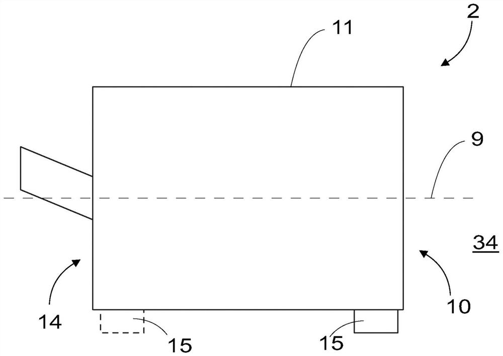
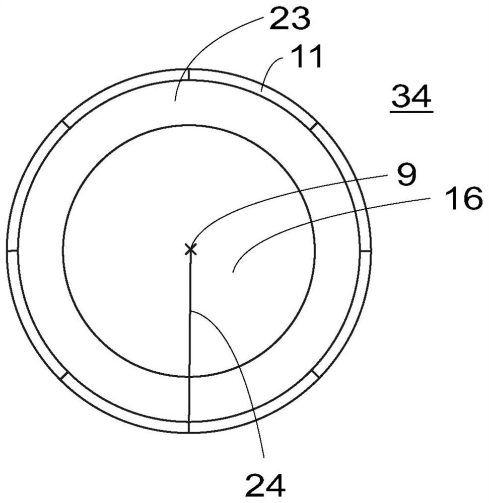
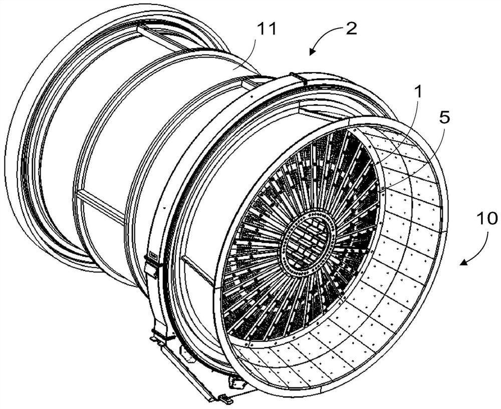
[0046] figure 1 A grinder 2 is shown schematically. figure 2 The grinder 2 is schematically shown viewed from the second end 10 , in other words the discharge end 10 of the grinder. figure 1 and figure 2 Only some features of the grinder 1 are shown which are helpful for understanding the present solution. It will be clear to a person skilled in the art that the grinder can, and often does, include other features as well.

[0047] Grinder 2 (e.g., figure 1 The grinder) comprises a drum comprising a cylindrical housing 11. In the grinder 2 of the present solution, the longitudinal axis 9 of the drum is arranged in a substantially horizontal position in the use position of the grinder 2 . By longitudinal axis 9 of the drum is meant the axis extending along the center line of the shell 11 from one end of the cylindrical shell to the other. The horizontal position refers to the longitudinal axis 9 extending in a substantially horizontal direction. In other words, the long...


PUM


Abstract

A lifter bar (32) for an open-ended grinding mill (2) comprises an elongated bar structure (45) and at least one groove portion (33) provided in the elongated bar structure (45). The groove portion (33) is configured to open on the side of the lifter bar (32) facing outwards from the grinding mill volume (28), when the lifter bar is mounted onto the grinding mill (2). The groove portion (33) is provided with at least one through hole opening (41) for a mounting member (48). The disclosure also provides an arrangement at a grinding mill discharge end and a method for disassembling a discharge end of a grinding mill.

Description

technical field [0001] The present invention relates to a grinder, in particular to a lifter bar (lifter bar), an arrangement at a discharge end (discharge end) of a grinder and a method for disassembling the discharge end of a grinder. Background technique [0002] Grinding mills, especially semi autogenous mills and autogenous mills, are capable of generating impacts that break ore charge (ore charge) and convey the ground material out of the mill through a discharge elevator. Increasing the diameter of the mill and the flow rate of the discharge generally limits the performance of the mill by limiting the material transfer rate and grinding efficiency. This is due to the inability to convey ground material through grates and slurry elevators, thereby limiting transfer rates due to slurry backflow / short circuits and carry over. The impact of this limitation on mill flow rate is a reduction in mill performance (product size) as the resulting pool of slurry will affect the ...

Claims


Application Information

Patent Timeline
Patent Type & Authority Applications(China)
IPC IPC(8): B02C23/00
CPCB02C23/00B02C17/1855B02C17/1825
Inventor N·格林D·博尔迪T·塔尼P·尼尔森
Owner METSO OUTOTEC METALS OY
Why Eureka
Try Eureka