Auxiliary fixing equipment for spot welding of electronic elements

A technology for fixing equipment and electronic components, applied in the field of auxiliary fixing equipment for spot welding of electronic components, can solve the problems of inconvenient fixing and loosening of circuit boards, affecting the normal operation of circuit boards, etc., to achieve convenient feeding and unloading work, convenient The effect of loading and unloading

Active Publication Date: 2022-02-25
SHENZHEN CHUANGJINGRUI ELECTRONICS
View PDF8 Cites 3 Cited by
  • Summary
  • Abstract
  • Description
  • Claims
  • Application Information

AI Technical Summary

Problems solved by technology

[0003] However, when the traditional electronic components are spot welded with the circuit board, they are placed individually at the bottom of the spot welder for welding, and the back and forth operation is time-consuming and labor-intensive, which reduces the efficiency of welding, and is inconvenient when placing the circuit board. Fixed, loading and unloading is very cumbersome, if the installation is not firm, it will easily cause loosening during welding and cause false welding, which will affect the normal operation of the circuit board

Method used


Image

  • Auxiliary fixing equipment for spot welding of electronic elements
  • Auxiliary fixing equipment for spot welding of electronic elements
  • Auxiliary fixing equipment for spot welding of electronic elements

Examples


Embodiment Construction

[0031] In order to make the technical means, creative features, goals and effects achieved by the present invention easy to understand, the present invention will be further described below in conjunction with specific embodiments.

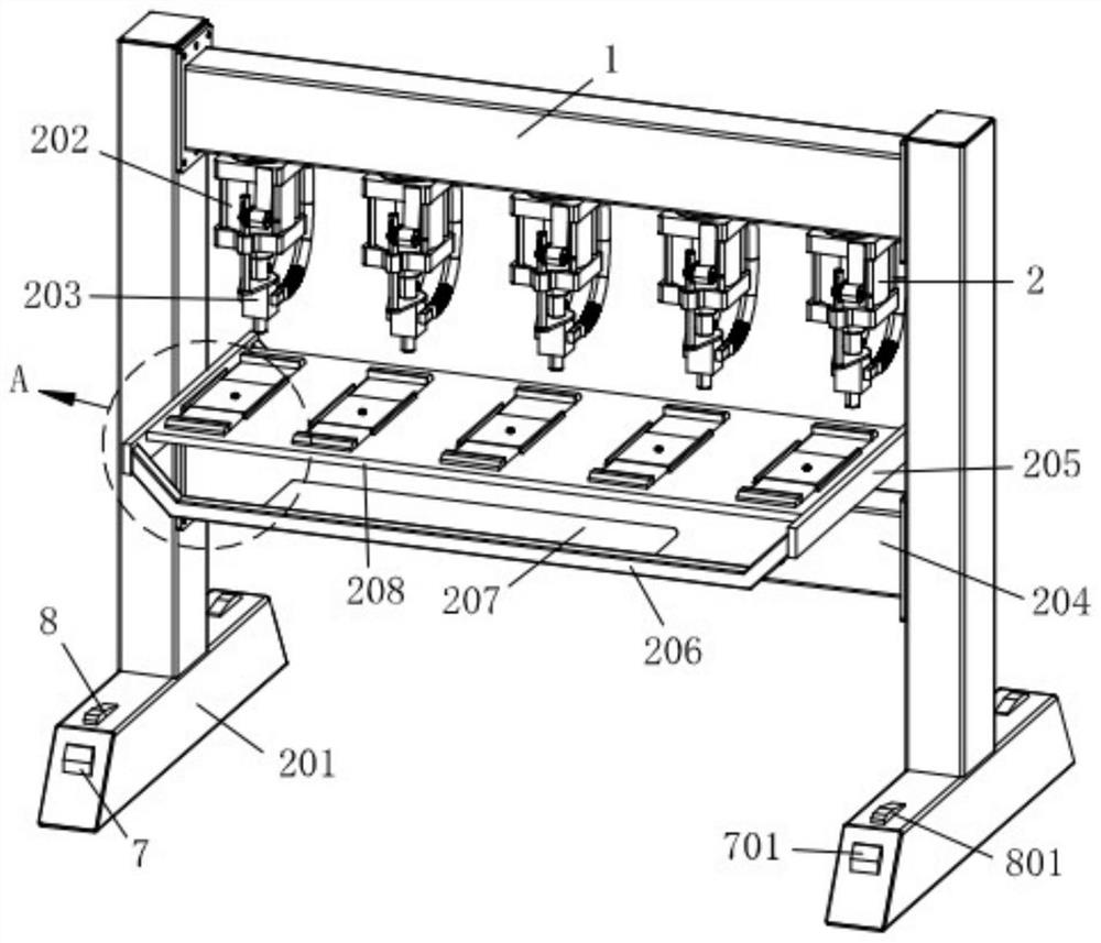
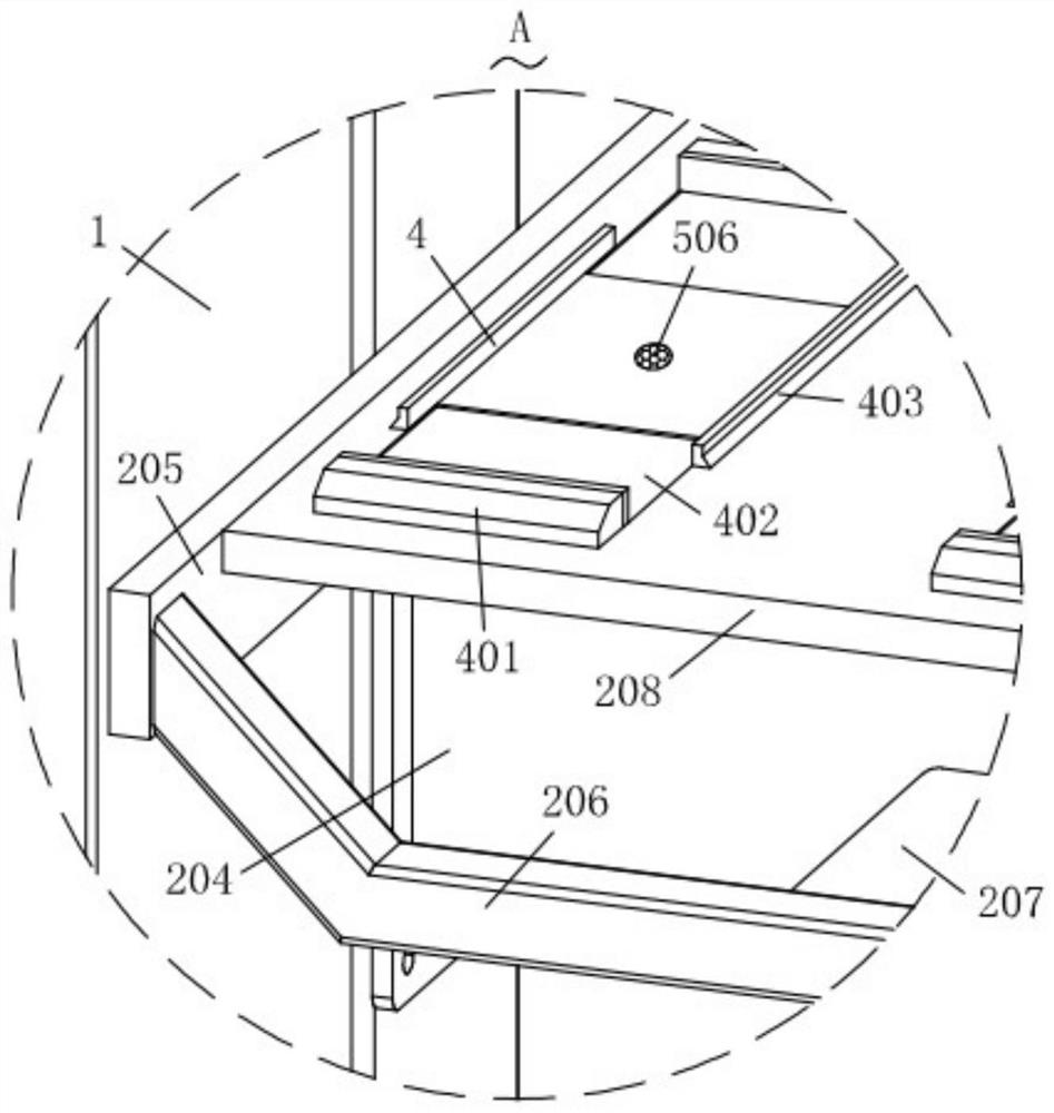
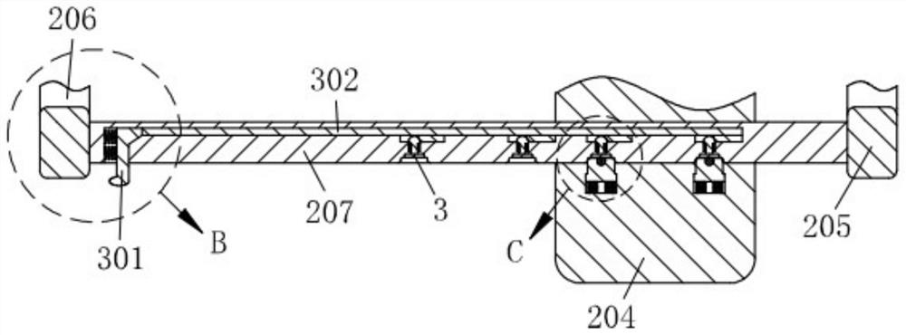
[0032] like Figure 1-Figure 9 As shown, an auxiliary fixing device for spot welding of electronic components according to the present invention includes a support frame 1, a welding mechanism 2 is installed on the support frame 1, a limit mechanism 3 is installed on the welding mechanism 2, and the welding A plurality of clamping mechanisms 4 are installed on the mechanism 2, a gas injection mechanism 5 is connected to the welding mechanism 2, a control mechanism 6 is installed on the welding mechanism 2, a braking mechanism 7 is installed on the welding mechanism 2, An engaging mechanism 8 is connected to the welding mechanism 2 .

[0033] Specifically, the welding mechanism 2 includes a cylinder 202, and the support frame 1 is detachably conne...


PUM


Abstract

The invention relates to the technical field of spot welding of electronic components, in particular to auxiliary fixing equipment for spot welding of electronic components. The equipment comprises a support frame, a welding mechanism is mounted on the support frame, a limiting mechanism is mounted on the welding mechanism, a plurality of clamping mechanisms are mounted on the welding mechanism, a gas injection mechanism is connected to the welding mechanism, a control mechanism is mounted on the welding mechanism, a brake mechanism is mounted on the welding mechanism, and a clamping mechanism is connected to the welding mechanism. Through installation of the welding mechanism and the support frame, simultaneous welding work of a plurality of circuit board components is facilitated; under assistance of the limiting mechanism, feeding and discharging operation is facilitated, efficiency is improved; through feeding and discharging of the welding mechanism, the control mechanism and the gas injection mechanism control the clamping mechanism, clamping and loosening during feeding and discharging of a circuit board are achieved; and under the action of the braking mechanism and the clamping mechanism, braking control of the welding mechanism is facilitated, and the supporting frame is convenient to move and move.

Description

technical field [0001] The invention relates to the technical field of spot welding of electronic components, in particular to an auxiliary fixing device for spot welding of electronic components. Background technique [0002] Spot welding refers to the welding method that uses a columnar electrode to form a solder joint between the contact surfaces of two overlapping workpieces. During spot welding, the workpiece is first pressed to make close contact, and then the current is turned on. The contact part of the lower workpiece is melted, and after cooling, a solder joint is formed. When welding the components on the circuit board, it needs to be welded by a spot welding machine. [0003] However, when the traditional electronic components are spot welded with the circuit board, they are placed individually at the bottom of the spot welder for welding, and the back and forth operation is time-consuming and labor-intensive, which reduces the efficiency of welding, and is incon...

Claims


Application Information

Patent Timeline
Patent Type & Authority Applications(China)
IPC IPC(8): B23K11/36B23K37/04B23K11/11B23K11/31B23K101/42
CPCB23K11/36B23K37/0435B23K11/11B23K11/31B23K2101/42
Inventor 叶春锋钟开平李高银
Owner SHENZHEN CHUANGJINGRUI ELECTRONICS
Why Eureka
Try Eureka