Mold and injection molding machine for producing buffer injection molding part

A technology for injection parts and injection molds, applied in the fields of molds and injection molding machines, can solve the problems of missing or falling off of sponges, increasing the labor intensity of production personnel, affecting the assembly quality of line body air conditioners in the assembly workshop, and achieving low processing costs. , The effect of reducing labor intensity and preventing leakage and foolproof quality

Pending Publication Date: 2022-02-25
GREE ELECTRIC APPLIANCES WUHAN +1
View PDF0 Cites 0 Cited by
  • Summary
  • Abstract
  • Description
  • Claims
  • Application Information

AI Technical Summary

Problems solved by technology

[0003] However, in the actual production process of the line body in the assembly workshop, due to the small size of the adhesive sponge, the sponge is often missing or falling off, which affects the overall efficiency of the assembly line body and the assembly quality of the air conditioner; the incoming material of the sponge The transfer and garbage cleaning of sponge stickers have increased the labor intensity of the front-line production personnel. At present, in order to realize the assembly efficiency of the line body and simplify the production process of the line body in the assembly workshop, this mold for the production of buffer injection molded parts is invented to comprehensively improve Production efficiency and air conditioner assembly quality

Method used


Image

  • Mold and injection molding machine for producing buffer injection molding part
  • Mold and injection molding machine for producing buffer injection molding part
  • Mold and injection molding machine for producing buffer injection molding part

Examples


Embodiment example 1

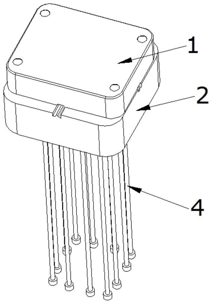
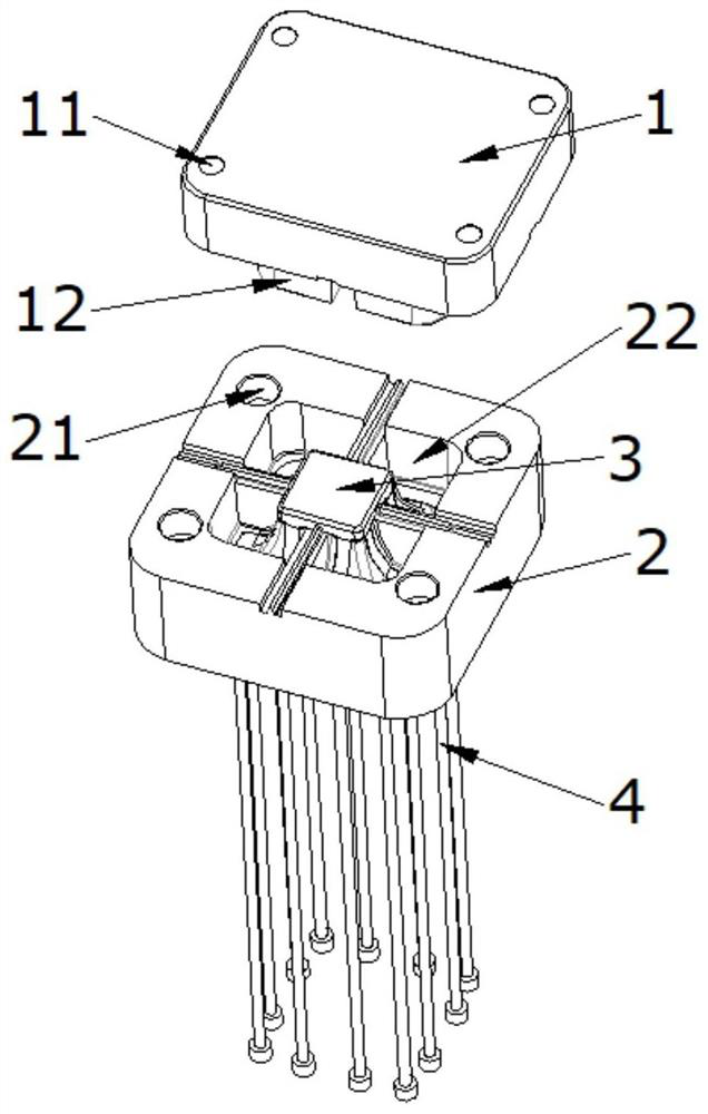
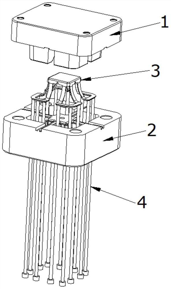
[0062] A mold for producing cushioning injection molded parts, comprising a fixed mold insert and a movable mold insert, the fixed mold insert and the movable mold insert are fixedly connected by a fixture; the fixed mold insert is provided with a bump, The movable mold insert is provided with a groove; the groove includes an accommodating cavity adapted to the bump, and the bump is inserted into the groove to form an injection mold cavity, which is used for injection molding to form a buffer injection model. The buffer injection molded part includes a base plate, one side of the base plate is connected with a buffer claw, and the base plate and the buffer claw are integrally formed by injection molding. There are 4 buffer claws. The buffer claw includes two buffer parts and a support part, the buffer part is arc-shaped, the support part is connected to one end of the buffer part, and the other end of the buffer part is connected to the substrate. By providing the support po...

Embodiment example 2

[0064] A mold for producing cushioning injection molded parts, comprising a fixed mold insert and a movable mold insert, the fixed mold insert and the movable mold insert are fixedly connected by a fixture; the fixed mold insert is provided with a bump, The movable mold insert is provided with a groove; the groove includes an accommodating cavity adapted to the bump, and the bump is inserted into the groove to form an injection mold cavity, which is used for injection molding to form a buffer injection model. The buffer injection molded part includes a base plate, one side of the base plate is connected with a buffer claw, and the base plate and the buffer claw are integrally formed by injection molding. There are at least two buffer claws. The number of buffer claws can be set according to actual needs. The buffer claw includes at least three buffer parts and a support part, the buffer part is arc-shaped, the support part is connected to one end of the buffer part, and the ...

Embodiment example 3

[0066] An injection molding machine for producing buffer injection molded parts, comprising the above-mentioned mold.

[0067] Main function of the present invention:

[0068] On the basis of the traditional mold parts, the present invention newly manufactures fixed mold inserts and movable mold inserts, uses the least mold modification process and the lowest mold processing cost, and directly replaces the dynamic, The fixed mold inserts and movable mold inserts on the fixed mold can be quickly switched, and converted into mass-produced protective net injection products with rebound and cushioning characteristics, without transfer and use of sponge materials, eliminating the need for manual pasting production processes, not only It optimizes the quality of leak-proof and fool-proof for the sponge sticking process, and also reduces the labor intensity of employees. In the present invention, the cushioning claw is provided on the cushioning injection molded parts, so that the i...


PUM


Abstract

The invention discloses a mold and an injection molding machine for producing a buffer injection molding part. The mold comprises a fixed mold insert and a movable mold insert, and the fixed mold insert and the movable mold insert are fixedly connected through a fixing part; the fixed mold insert is provided with a convex block, and the movable mold insert is provided with a groove; and the groove comprises a containing cavity matched with the protruding block, the protruding block is inserted into the groove to form an injection mold cavity, and the injection mold cavity is used for injection molding to form a buffering injection molding part. On the basis of traditional mold parts, the fixed mold insert and the movable mold insert are newly manufactured, the fewest mold changing procedures and the lowest mold machining cost are used, and on the basis of an original injection protection net mold, rapid switching can be achieved by directly replacing the fixed mold insert and the movable mold insert on the movable mold and the fixed mold of the mold; and the traditional mode is converted into a mass-produced protective net injection product with resilience and buffering characteristics, and sponge materials do not need to be transferred and used, so that the production procedure of manual pasting is omitted, and the labor intensity of workers is reduced.

Description

technical field [0001] The invention relates to the technical field of moulds, in particular to a mold and an injection molding machine for producing buffer injection molded parts. Background technique [0002] At present, many injection molding products of the company's protective nets will use sponges to protect the product assembly from stress and deformation. [0003] However, in the actual production process of the line body in the assembly workshop, due to the small size of the adhesive sponge, the sponge is often missing or falling off, which affects the overall efficiency of the assembly line body and the assembly quality of the air conditioner; the incoming material of the sponge The transfer and garbage cleaning of sponge stickers have increased the labor intensity of the front-line production personnel. At present, in order to realize the assembly efficiency of the line body and simplify the production process of the line body in the assembly workshop, this mold f...

Claims


Application Information

Patent Timeline
IPC IPC(8): B29C45/36B29C45/40
CPCB29C45/36B29C45/401B29C45/2673
Inventor 吴彬李爽李超焦海波郭辉盛
Owner GREE ELECTRIC APPLIANCES WUHAN
Why Eureka
Try Eureka