Framework, bogie and railway vehicle

A bogie and frame technology, which is applied in the field of rail vehicles and can solve problems such as complex structures

Pending Publication Date: 2022-02-25
CRRC QINGDAO SIFANG CO LTD
View PDF9 Cites 1 Cited by
  • Summary
  • Abstract
  • Description
  • Claims
  • Application Information

AI Technical Summary

Problems solved by technology

There is an empty spring in the middle of the side beam of the bogie, and the inner cavity of the side beam forms an additional air chamber for the air spring. When the volume is insufficient, an external bellows is also used as an additional air chamber, and the structure is more complicated.

Method used


Image

  • Framework, bogie and railway vehicle
  • Framework, bogie and railway vehicle
  • Framework, bogie and railway vehicle

Examples


Embodiment 2

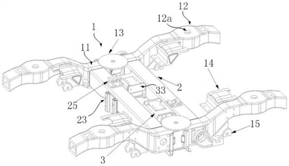
[0107] Please refer to Figure 20 , Figure 20 It is a schematic structural diagram of the bogie frame in Embodiment 2 provided by the present invention.

[0108] The frame structure of embodiment 2 is basically the same as that of embodiment 1, the only difference lies in the structure of the end beam body 12 of the side beam 1, and the same parts will not be repeated.

[0109] Such as Figure 20 As shown, the side beam 1 in Embodiment 2 includes a box-shaped main beam body 11, that is, the main beam body 11 is a hollow box-shaped structure. What is different from Embodiment 1 is that the end beam body in Embodiment 2 12 is a plate structure, specifically, Figure 20 The end beam body 12 is a strip plate structure.

[0110] The plate-shaped end beam body 12 at the end of the side beam 1 is used to connect with a series of springs, and the first series of springs are located below the end beam body 12 . In this way, the main beam body 11 of the side beam 1 is used as the ...

Embodiment 3

[0119] Please refer to Figure 21 , Figure 21 It is a schematic structural diagram of the side beam 1 of the bogie frame in Embodiment 3 provided by the present invention.

[0120] It is basically the same as Embodiment 2, the only difference is that the end beam body 12 is a straight strip plate without bending treatment. When the end beam body 12 is designed to be relatively short, no bending treatment is required, and it can Avoid interference with the vehicle body. The molding process can be understood with reference to Example 2.

Embodiment 4

[0122] Please refer to Figure 22 , 23 , Figure 22 A schematic structural view of the bogie frame in Embodiment 4 provided by the present invention; Figure 23 for Figure 22 Schematic diagram of the middle side beam 1.

[0123]The framework structure of embodiment 2 is basically the same as that of embodiment 2-3, the difference is that the structure of the end beam body 12 and the end beam body 12 and the main beam body 11 are arranged separately, the same parts will not be repeated, and the main differences will be described below part.

[0124] Such as Figure 23 As shown, the main beam body 11 and the end beam body 12 in Embodiment 4 are arranged separately, and the main beam body 11 is made of fiber composite material, and the end beam body 12 is made of metal. The end beam body 12 is also a plate-shaped structure, and its function is the same as that of the plate-shaped end beam body 12 in Embodiments 2 and 3.

[0125] Figure 23 Among them, the end beam body 1...


PUM


Abstract

The invention discloses a framework, a bogie and a railway vehicle, the framework comprises two side beams and two cross beams connected between the two side beams, air springs of the bogie are installed on the side beams, at least one auxiliary beam is connected between the two cross beams, an inner cavity of the auxiliary beam is divided into a first cavity and a second cavity, the first cavity is communicated with the inner cavity of one cross beam to jointly serve as an additional air chamber of one air spring, and the second cavity is communicated with the inner cavity of the other cross beam to jointly serve as an additional air chamber of the other air spring. According to the scheme, the auxiliary beam of the bogie and the framework not only serves as a connecting piece for connecting the front cross beam and the rear cross beam, but also is divided into the first cavity and the second cavity at the same time and can be communicated with the inner cavities of the cross beams, so that the auxiliary beam serves as the additional air chambers of the air springs installed on the bogie and the framework, the volume of the additional air chambers is increased, and the structure of the framework is simplified.

Description

technical field [0001] The invention relates to the technical field of rail vehicles, in particular to a frame, a bogie and a rail vehicle. Background technique [0002] At present, in rail vehicles, such as subways, EMUs, high-speed rail, etc., the side beams and beams of the bogie frame are basically made of metal materials, and the auxiliary beam of the bogie is a part of the bogie beam, and the auxiliary beam is welded between the two beams. between. There is an empty spring in the middle of the side beam of the bogie, and the inner cavity of the side beam forms an additional air chamber for the air spring. When the volume is insufficient, an external bellows is also used as an additional air chamber, and the structure is relatively complicated. [0003] In view of this, how to improve the frame design of the bogie is a technical problem to be solved by those skilled in the art. Contents of the invention [0004] The frame provided by the present invention includes t...

Claims


Application Information

Patent Timeline
IPC IPC(8): B61F5/52
CPCB61F5/52B61F5/523Y02T30/00
Inventor 丁叁叁高玉龙孙厚礼王晓明张雄飞陈东方王石张联合肖鹏张义阮大卫
Owner CRRC QINGDAO SIFANG CO LTD
Why Eureka
Try Eureka