
Winding, bundling and positioning structure based on automobile wire harness

A technology of automobile wiring harness and positioning structure, which is applied to the parts and packaging of bundling machinery, can solve the problems of harming the body of operators, heavy workload of workers, low efficiency, etc., so as to reduce labor costs, workload, and labor. The effect of time of operation

Active Publication Date: 2022-02-25
NANCHANG YOUXING ELECTRONICS & ELECTRICAL APPLIANCE
View PDF5 Cites 0 Cited by
  • Summary
  • Abstract
  • Description
  • Claims
  • Application Information

AI Technical Summary

Problems solved by technology

[0004] The purpose of the present invention is to overcome the need to manually fix the binding steel wires in the existing binding structure, which will endanger the operator's body during binding, while the existing binding structure The efficiency of the binding work is low, and the workload of the workers is relatively large. It provides a high degree of automation, which is not easy to harm the body of the workers, and is simple to operate and high in efficiency.

Method used


Image

  • Winding, bundling and positioning structure based on automobile wire harness
  • Winding, bundling and positioning structure based on automobile wire harness
  • Winding, bundling and positioning structure based on automobile wire harness

Examples


Embodiment 1

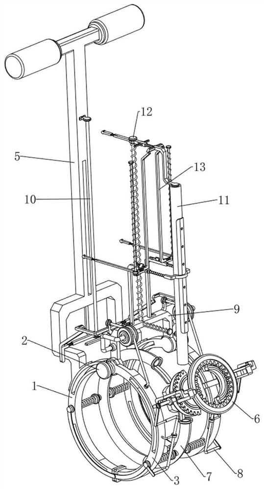
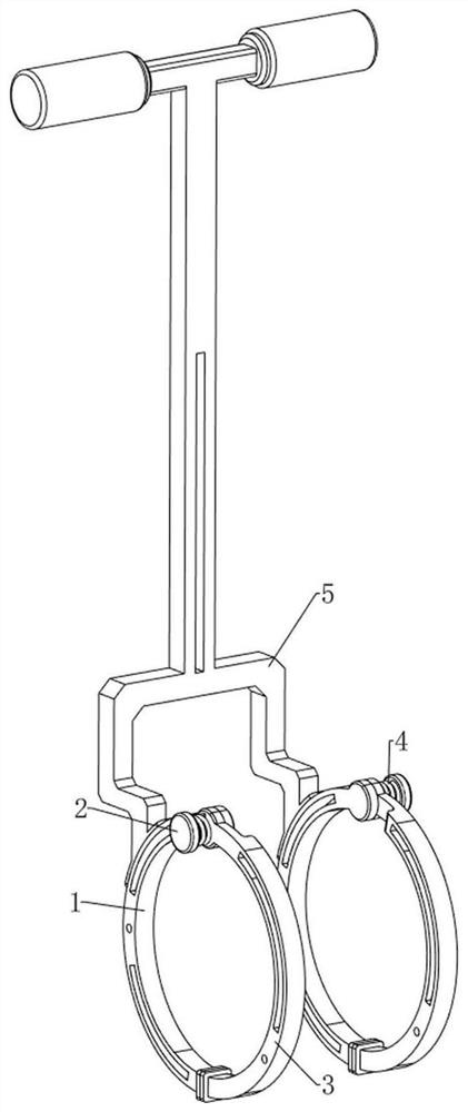
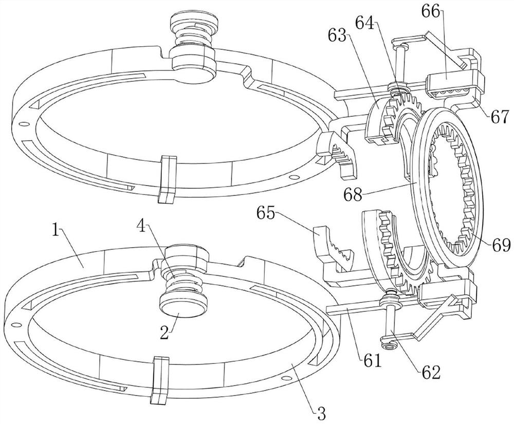
[0042] A structure based on the winding and bundling of automobile wire harnesses and its positioning, such as Figure 1-7 As shown, it includes a first positioning ring 1, a first connecting rod 2, a second positioning ring 3, a torsion spring 4, a connection handle 5, a binding mechanism 6, a guiding mechanism 7 and a pulling mechanism 8. The first positioning ring 1 There are two in total, the two first positioning rings 1 are placed symmetrically front and back, the upper sides of the two first positioning rings 1 are welded with the first connecting rod 2, and the two first connecting rods 2 are provided with the second positioning through the rotating shaft Ring 3, the torsion spring 4 is connected between the two second positioning rings 3 and the first connecting rod 2 on the same side, the two second positioning rings 3 are in contact with the first positioning ring 1 on the same side, the first positioning A connection handle 5 is welded between the upper sides of th...

Embodiment 2

[0048] On the basis of Example 1, such as figure 1 , Figure 8 , Figure 9 , Figure 10 , Figure 11 , Figure 12 , Figure 13 , Figure 14 , Figure 15 , Figure 16 , Figure 17 and Figure 18 As shown, an opening mechanism 9 is also included, and the opening mechanism 9 includes a second connecting block 91, a pulley 92, a second connecting rod 93, a third connecting block 94, a pull cord 95, a fourth return spring 96 and a fourth connecting block 97, a second connecting block 91 is welded between the tops of the two first positioning rings 1, the upper side of the second connecting block 91 is rotatably equipped with pulleys 92 on the front and rear sides, and the sliding type in the middle of the second connecting block 91 is provided with a second Connecting rod 93, the third connecting block 94 is welded on the left side of the second connecting rod 93, the fourth return spring 96 is connected between the second connecting rod 93 and the second connecting block 9...


PUM


Abstract

The invention relates to a positioning structure, in particular to an automobile wire harness rolling and bundling and positioning structure. The winding, bundling and positioning structure based on the automobile wire harness is high in automation degree, not prone to harming the body of a worker, easy to operate and high in working efficiency. A winding, bundling and positioning structure based on automobile wire harnesses comprises two first positioning rings, first connecting rods, second positioning rings, torsion springs and the like, the two first positioning rings are symmetrically arranged front and back, the first connecting rods are arranged on the upper sides of the two first positioning rings, and the torsion springs are arranged on the first connecting rods. Second positioning rings are rotationally arranged on the two first connecting rods correspondingly, and torsion springs are connected between the two second positioning rings and the first connecting rods on the same sides. The electric rotating rail rotates to drive the inner gear and the outer gear to rotate, then the bundling clamp is driven to rotate, the bundling clamp drives the two ends of the steel wire to rotate to tighten the wire harness, and therefore the steel wire can be tightened manually without a tool.

Description

technical field [0001] The invention relates to a positioning structure, in particular to a winding and bundling structure based on automobile wire harnesses and its positioning structure. Background technique [0002] Since the 21st century, people's living standards have been continuously improved, and the development of science and technology has also become increasingly rapid, especially the development of automobile technology. At the same time, people's demand for cars is also increasing day by day. Cars have become daily necessities for every household. Therefore, how to quickly assemble the car as a whole is particularly important, especially because there are many internal wiring harnesses in the car. The bundling is relatively cumbersome. People mainly rely on the manual use of the bundling structure to bundle the wire harness when winding and bundling the wire harness. However, the existing bundling structure often needs to manually fix the bundling steel wire whe...

Claims


Application Information

Patent Timeline
IPC IPC(8): B65B13/18B65B27/06
CPCB65B13/18B65B27/06
Inventor 葛小可梅志强黄思伟
Owner NANCHANG YOUXING ELECTRONICS & ELECTRICAL APPLIANCE
Learn More