
Eureka
For R&D, Eureka makes reading and utilizing patents & technical documents easy.
Eureka AIR
Designed for self-driven R&D workflows. Generate viable solutions, solve complex R&D challenges, empower your innovation with AI.

Eureka Materials
Designed for material experts only. Revolutionize your material R&D, from search, analyze, to developing new materials.

TechResearch
Generate reliable direction feasibility study reports for your R&D in just a few steps.

TechSeek
Discover and master advanced knowledge NOW. Basics, ideas, possibilities, all at once.

TechMind
As an expert in R&D Theories, TechMind can generates customized viable solutions instantly.

TechRisk
Analyze your overall solution with one click, know your potential R&D risks in advance.

TechMonitor
Get weekly tech updates, stay abreast of the latest tech innovations and key insights.
Self-control rain and sewage diversion device
A rain and sewage diversion and confluence pipe technology, applied in water supply devices, grease/oily substance/float removal devices, water/sewage treatment, etc. And other issues
- Summary
- Abstract
- Description
- Claims
- Application Information
AI Technical Summary
Problems solved by technology
Method used
Image

Examples
Embodiment 1
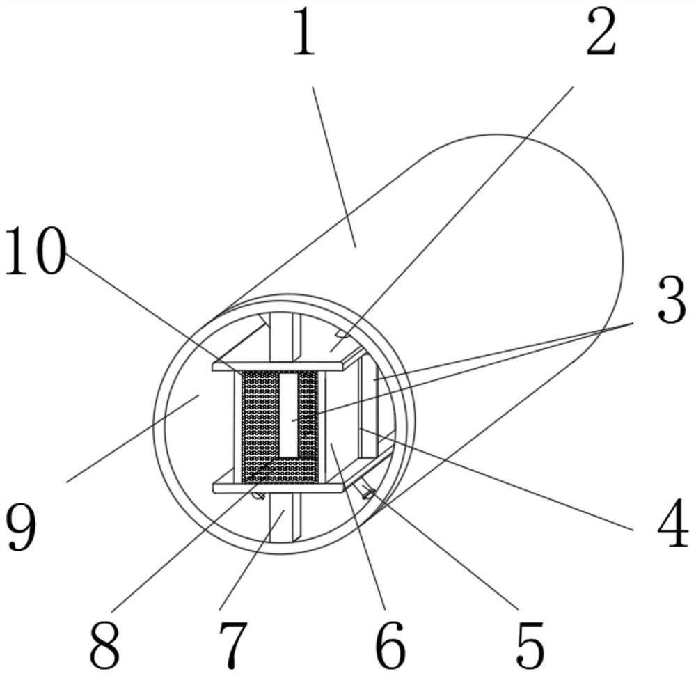
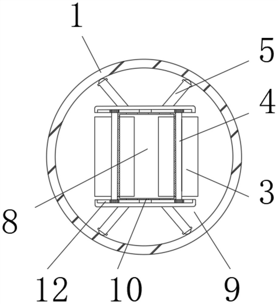
[0038] Such as Figure 1-12 As shown, a self-controlled rain and sewage diversion device includes a confluence pipe (1), and an outflow chamber (9) is opened inside the confluence pipe (1), and the outflow chamber (9) is provided with a fixing part, and the fixation The parts are cascaded with each other by providing movable parts, the middle part of the fixed part and the movable part is formed with an inner flow cavity (8), and the two sides of the movable part are provided with flow sensing paddles (3), The flow sensing paddle (3) is connected with a driving part that controls the volume change of the inner flow cavity (8), and one end of the fixed part is fixedly connected with a fixed strut (5), and the fixed strut (5) is away from the fixed One end of the part is attached to the inner wall of the confluence pipe (1), and the fixed part is fixedly connected with the confluence pipe (1) through a fixing piece (7).
[0039] When in use, the outflow chamber (9) inside the c...
Embodiment 2
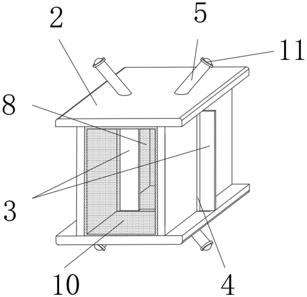
[0041] On the basis of Example 1, as Figure 1-3 As shown, the inside of the inner flow cavity (8) is fitted with an elastic sealing layer (10), and one end of the fixed strut (5) fitted with the confluence pipe (1) is movably embedded with a movable ball (11) .
[0042] When in use, the elastic sealing layer (10) can be made of elastic material, and a movable ball (11) is provided so that the fixed part can slide inside the confluence pipe (1) through the movable ball (11) during installation. After sliding to a suitable position, the fixed part is positioned by the fixing part (7), without re-excavating and embedding the pipeline, the construction is more convenient, and the installation cost is lower.
[0043] Such as Figure 1-3 As shown, the fixed part is specifically a support plate (2), the movable part is specifically an adjustable plate (6), the support plate (2) and the adjustable plate (6) are perpendicular to each other, and the adjustable plate (6) is slidably ...
Embodiment 3
[0049] On the basis of Example 1, as Figure 7-12 As shown, the movable part is specifically an elastic arc-shaped plate (17), and the fixed part is specifically a fixed rod (18).
[0050] Such as Figure 7-12 As shown, the drive part includes a drive plate (19), a drive slide bar (20), a second movable slot (21) and a connecting rod (23), and the connecting rod (23) is elastically embedded in the elastic arc plate (17), the second movable groove (21) is set inside the connecting rod (23), and the two ends of the driving plate (19) are fixedly connected with the fixed rod (18) (not shown in the figure), The driving slide bar (20) is elastically connected to the middle part of the second movable groove (21) through a spring (22).
[0051] Such as Figure 7-12 As shown, the inside of the drive plate (19) is provided with a drive slot (24) compatible with the drive slide bar (20), and the drive slot (24) is inclined relative to the elastic arc plate (17), The current-sensing ...
PUM
 Abstract
Description
Claims
Application Information
 - R&D Engineer
- R&D Manager
- IP Professional
- Industry Leading Data Capabilities
- Powerful AI technology
- Patent DNA Extraction
Browse by: Latest US Patents, China's latest patents, Technical Efficacy Thesaurus, Application Domain, Technology Topic, Popular Technical Reports.
© 2024 PatSnap. All rights reserved.Legal|Privacy policy|Modern Slavery Act Transparency Statement|Sitemap|About US| Contact US: help@patsnap.com