
An air compressor oil and gas waste heat recycling device

An air compressor, oil and gas technology, applied in the direction of mechanical equipment, machines/engines, liquid displacement machinery, etc., can solve the problem of easy accumulation of oil and achieve good oil discharge effect

Active Publication Date: 2022-06-21
华海(北京)科技股份有限公司
View PDF0 Cites 0 Cited by
  • Summary
  • Abstract
  • Description
  • Claims
  • Application Information

AI Technical Summary

Problems solved by technology

[0005] In order to improve the problem of easy accumulation of oil in the ventilation pipe of the heat recovery device in the related art, this application provides an air compressor oil and gas waste heat recycling device

Method used


Image

  • An air compressor oil and gas waste heat recycling device
  • An air compressor oil and gas waste heat recycling device
  • An air compressor oil and gas waste heat recycling device

Examples


Embodiment Construction

[0039] Attached to the following Figure 1-3 This application will be described in further detail.

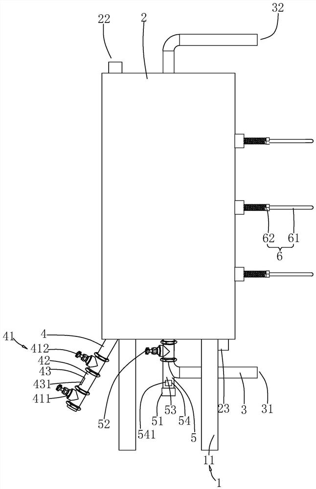
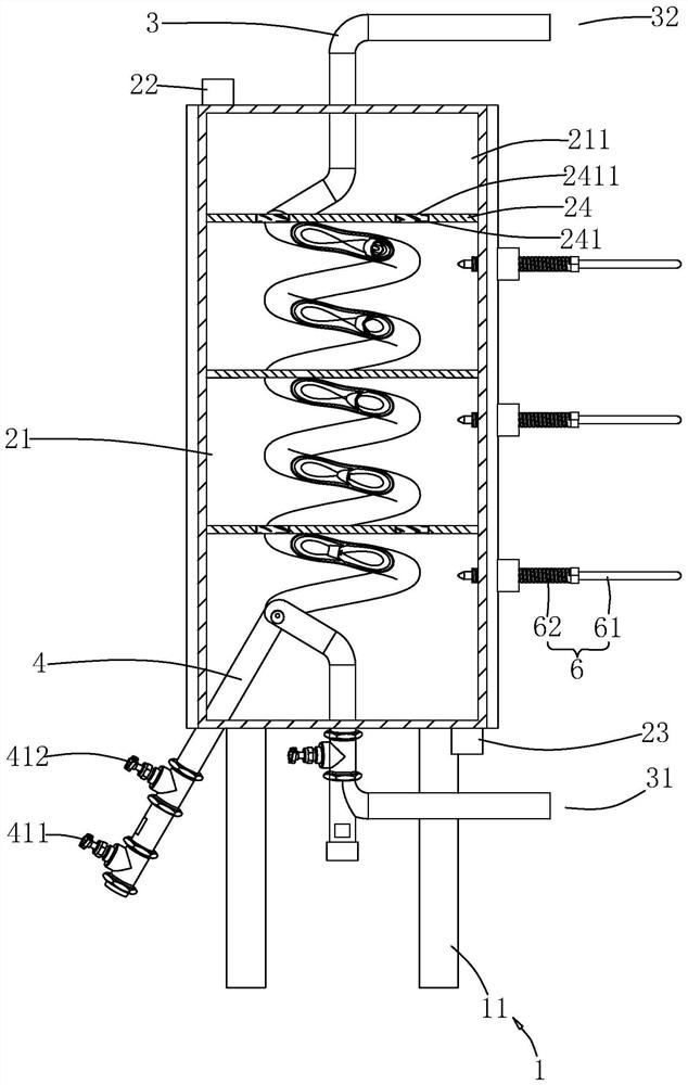
[0040] The embodiment of the present application discloses a device for reusing oil and gas waste heat of an air compressor. refer to figure 1 , including the bracket 1, the water tank 2 and the ventilation pipe 3. The ventilation pipe 3 is placed in the water passing tank 2 , two ends of the ventilation pipe 3 respectively extend out of the water passing tank 2 , and the ventilation pipe 3 and the water passing tank 2 are fixedly connected. One end of the ventilation pipe 3 is an air inlet 31 , and the other end of the ventilation pipe 3 is an air outlet 32 ​​.

[0041] refer to figure 2 , the outer surface of the ventilation pipe 3 and the inner surface of the water tank 2 form a water passage cavity 21 .

[0042] The water passage tank 2 is supported on the ground by a bracket 1 , and the bracket 1 includes four outriggers 11 , which are all fixed to the bottom of the ...


PUM


Abstract

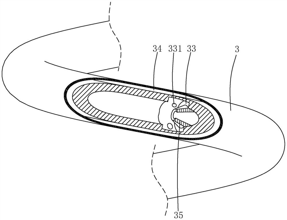
The invention relates to an air compressor oil and gas waste heat recycling device, relates to air compressor waste heat recovery technology, including a water tank and a vent pipe; the water tank is provided with a water inlet and a water outlet; the vent pipe is located at In the water tank, and the two ends of the ventilation pipe are stretched out from the water tank; one end of the ventilation pipe is an air inlet, and the other end of the ventilation pipe is an air outlet; the ventilation pipe An oil discharge channel is provided inside, and a number of oil discharge holes communicating with the oil discharge channels are opened on the inner wall of a plurality of the ventilation pipes; an oil discharge pipe is fixedly connected to the ventilation pipe, and the oil discharge pipe and the The oil channel is connected, the end of the oil discharge pipe away from the ventilation pipe extends out of the water tank, and the part of the oil discharge pipe extending out of the water tank is equipped with a valve body. The application has the effect of reducing oil accumulation in the vent pipe.

Description

technical field [0001] The present application relates to the technology of recycling and utilizing the waste heat of air compressors, and in particular, to a device for reusing the waste heat of oil and gas of an air compressor. Background technique [0002] The full name of the air compressor is the air compressor. It is the main body of the air source device. It is a device that converts the mechanical energy of the motor, commonly known as the electric motor, into gas pressure, and is an air pressure generating device for compressing air. In the process of compressing the air in the air compressor in the related art, since the motor will do work, a relatively large amount of heat will be generated in this process. In order to save energy, a heat recovery device for recovering the heat in the air flow is often installed at the air outlet of the air compressor. The heat recovery device generally includes a water tank. The water tank is provided with a water inlet and a wat...

Claims


Application Information

Patent Timeline
Patent Type & Authority Patents(China)
IPC IPC(8): F04B39/00
CPCF04B39/00
Inventor 吴思明冯向阳吴振业
Owner 华海(北京)科技股份有限公司
Learn More