Device and method for remote joint test of electronic equipment

An electronic device and remote technology, applied in the electronic field, can solve the problems of difficult site adjustment, high cost, and different distances, and achieve the effects of shortening the work cycle, improving work efficiency, and ensuring phase noise

Active Publication Date: 2022-02-25
SOUTHWEST CHINA RES INST OF ELECTRONICS EQUIP
View PDF3 Cites 0 Cited by
  • Summary
  • Abstract
  • Description
  • Claims
  • Application Information

AI Technical Summary

Problems solved by technology

[0003] 1) The joint test requires a variety of equipment, multiple sub-systems, etc. to work together, and the shapes of the equipment are different, and the workload of logistics and transfer to the joint test site is relatively large
And if the joint test is staged, multiple round-trip transportation is required, which is inefficient;
[0004] 2) The joint test can only be started after all the sub-systems have completed their own debugging and testing. The debugging and testing progress of individual sub-systems will directly affect the progress of the joint testing of the entire system;
[0005] 3) It is necessary for the support resources and personnel of each subsystem to arrive at the joint test site
Moreover, in most cases, the independent debugg

Method used


Image

  • Device and method for remote joint test of electronic equipment
  • Device and method for remote joint test of electronic equipment
  • Device and method for remote joint test of electronic equipment

Examples


Embodiment 1

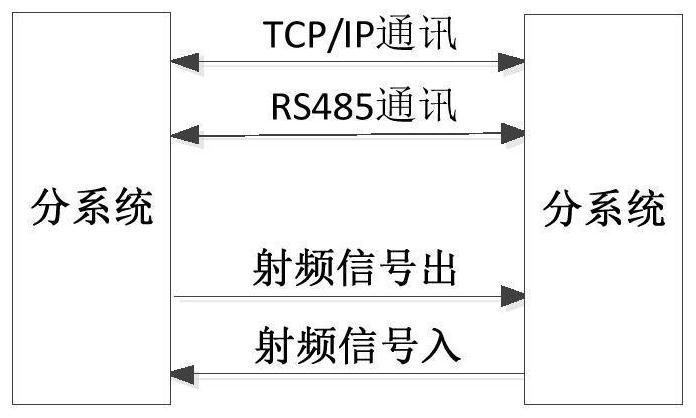
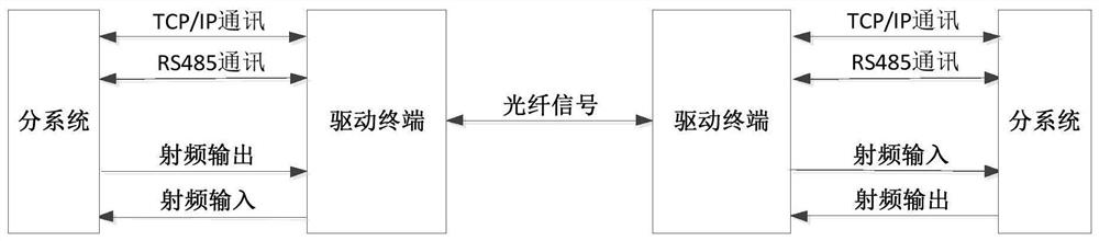
[0035] Embodiment 1: as figure 1 As shown, a device for remote joint testing of electronic equipment is composed of multiple drive terminals connected to each other through optical fibers. At least one drive terminal is installed at each subsystem participating in the system joint test to connect the communication and radio frequency signals of the subsystems. After the drive terminal converts these signals into optical signals, they are combined on an optical fiber and transmitted to another drive terminal in the distance. The drive terminal converts the optical signals into corresponding radio frequency and communication signals, and Cross-linking with distant subsystems, such as figure 2 shown.

Embodiment 2

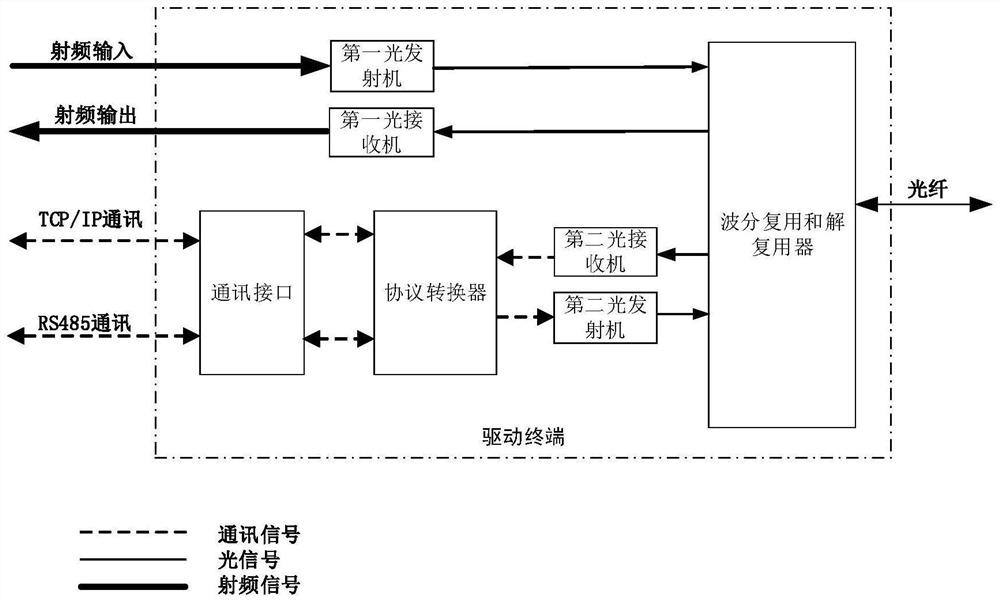
[0036] Embodiment 2: On the basis of Embodiment 1, in specific applications, the drive terminal is provided with one RS485 protocol communication interface, one TCP / IP protocol communication interface, one radio frequency signal output, and one radio frequency signal input. During implementation, the communication protocol is not limited to this, it can be other communication protocols with a bandwidth not greater than 200Mbps, and the number of interfaces is not limited to this. The composition of the drive terminal is as follows image 3 Schematically, the working principle is as follows:

[0037] The first optical transmitter and the first optical receiver, in the first optical transmitter, the carrier optical signal is first generated by the laser, and then the input electrical signal is modulated onto the carrier optical signal and output; the first optical receiver converts the input optical signal The modulated electrical signal in the signal is demodulated and output ...


PUM


Abstract

The invention discloses a device and a method for remote joint test of electronic equipment, and relates to the technical field of electronics, the electronic equipment remote joint test device comprises a plurality of driving terminals, the plurality of driving terminals are connected through optical fibers, each subsystem participating in system joint test is provided with at least one driving terminal, and communication and radio frequency signals of the subsystems are connected to the driving terminals. The driving terminal converts communication and radio frequency signals of the subsystem into optical signals, then the optical signals are compounded to an optical fiber and transmitted to another driving terminal at the distance, and the driving terminal converts the optical signals into corresponding radio frequency and communication signals and is crosslinked with the subsystem at the distance. The system supports communication signals and radio frequency signals at the same time and can be used in a long distance, so that subsystems can be distributed in respective sites and do not need to be concentrated in one place during system joint test, the working efficiency is improved, the cost-effectiveness ratio is reduced, and the working period is shortened.

Description

technical field [0001] The present invention relates to the field of electronic technology, and more specifically, to a device and method for remote joint testing of electronic equipment. Background technique [0002] A system in the traditional sense is generally composed of several sub-systems that realize a single task, and the sub-systems are cross-linked through radio frequency signals and digital signals. In system research and development, production and maintenance, etc., it is necessary to connect the subsystems for joint operation and testing, that is, system joint test (referred to as joint test). Since there is an electrical connection relationship between communication and radio frequency signals between subsystems, the length of the connecting cable will affect the electrical indicators, such as radio frequency signals, the longer the connecting cable, the greater the signal loss. Therefore, when the system is tested together, it is usually required to gather ...

Claims


Application Information

Patent Timeline
IPC IPC(8): H04B10/075H04B10/69
CPCH04B10/075H04B10/697
Inventor 任锋李钊戴健刘威刘衡
Owner SOUTHWEST CHINA RES INST OF ELECTRONICS EQUIP
Why Eureka
Try Eureka