Multi-port direct current energy router

A router, multi-port technology, applied in the direction of instruments, springs/shock absorbers, chemical instruments and methods, etc., can solve the problems of excessive rotation of the antenna and the effect of light on the user's sleep, so as to avoid accidental damage and avoid excessive rotation of the antenna. Effect

Inactive Publication Date: 2022-02-25
王玉林
View PDF0 Cites 0 Cited by
  • Summary
  • Abstract
  • Description
  • Claims
  • Application Information

AI Technical Summary

Problems solved by technology

[0005] The purpose of the present invention is to provide a multi-port DC energy router, which can provide effective shock absorption protection for the router, and automatically realize the effect of pneumatic dust removal by using the kinetic energy during impact. In addition, it can avoid the effect of excessive rotation of the antenna caused by accidental touch, ensuring The antenna is in a suitable working position, and at the same time, it solves the problem that the light affects the user's sleep

Method used


Image

  • Multi-port direct current energy router
  • Multi-port direct current energy router
  • Multi-port direct current energy router

Examples


Embodiment 1

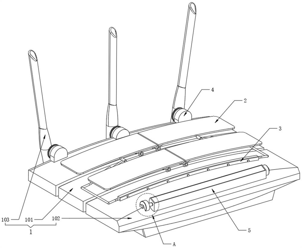
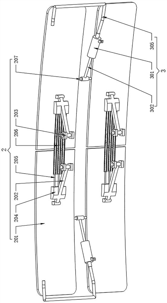
[0041] Refer to attached image 3The two sets of protective structures 2 all include two top guards 201 inside, and the two sets of two top guards 201 are oppositely arranged, and the lower surfaces of the top guards 201 are connected with tilting rods 202 for rotation, and the upper surface of the body 101 corresponds to The positions of the tilting rods 202 are fixedly provided with the same number of bottom swivel bases 203, and the ends of the tilting rods 202 are rotationally connected with the bottom swivel bases 203. When an object falls from above the router 1, each top guard plate 201 will After receiving the impact force, the top guard plates 201 on both sides drop to both sides respectively after bearing the impact. At this time, the oblique rotation rods 202 on both sides will respectively rotate with the bottom swivel base 203 as the center of circle, and the oblique rotation rods 202 on both sides will rotate respectively. The direction of rotation of the lever 2...

Embodiment 2

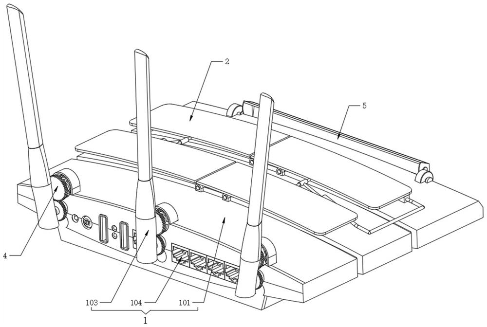
[0049] Refer to attached Image 6 , the self-locking assembly 4 also includes a lock housing 402, the lock housing 402 is fixedly arranged on the back of the body 101, the back of the body 101 is located inside each lock housing 402 and is fixedly provided with a swivel seat 403, and the swivel seat 403 Rotating rods 404 are installed inside, and driven gears 405 are fixedly installed at one end of the rotating rods 404, and driving gears 401 are fixedly installed at the connection between the bottom end of the antenna 103 and the body 101, and the driving gears 401 and the driven gears 405 When the antenna 103 rotates rapidly due to the force, the driving gear 401 will rotate together with the antenna 103, and through the meshing of the driving gear 401 and the driven gear 405, the rotating rod 404 will rotate inside the rotating base 403 .

[0050] Refer to attached Figure 7 , the inside of the lock housing 402 is fixedly equipped with a groove ring body 407, the inner wa...

Embodiment 3

[0054] Refer to attached Figure 9 and Figure 10 , the light shield 5 also includes a light shield 501, the shape of the side surface of the light shield 501 is fan-shaped, the two ends of the light shield 501 are fixedly connected with deflection rods 504, and the ends of the two deflection rods 504 are fixedly connected with damping wheels 505, two damping runners 505 are all rotatably installed on the outer wall of the body 101, the inner wall of one side of the light shield 501 is fixedly provided with a reflector 502, and the other side wall of the light shield 501 is fixedly provided with a transparent plate 503, when the router 1 When used at night, in order to prevent the light on the surface of the display panel 102 from affecting the rest of the user, at this time, the manual rotation of the damping wheel 505 will drive the light shield 501 to rotate through the deflection rod 504. At this time, the light shield 501 The shading part of the display panel 102 will bl...


PUM


Abstract

The invention belongs to the technical field of routers, and particularly relates to a multi-port direct current energy router. The multi-port direct current energy router comprises a router, wherein protection structures are fixedly arranged on two sides of an upper surface of a body; a linkage dust removal assembly is fixedly arranged on the upper surface of the body; a self-locking assembly is fixedly arranged at a position, located on one side of each antenna, of an outer wall of the body; a light shielding device is arranged at a position, located on the outer surface of a display panel, of the body; two top protection plates are arranged in each protection structure; the two top protection plates are oppositely arranged; and inclined rotating rods are rotationally connected to lower surfaces of the top protection plates. According to the invention, effective damping protection can be provided for a router, and the pneumatic dust removal effect can be automatically realized by utilizing kinetic energy during collision. In addition, the effect of excessive rotation of antennas caused by accidental touch can be avoided, the antennas are ensured to be in proper working positions, and the problem that light affects sleep of a user is solved.

Description

technical field [0001] The invention belongs to the technical field of routers, and in particular relates to a multi-port DC energy router. Background technique [0002] A router is a hardware device that connects two or more networks. It acts as a gateway between networks. It is a dedicated intelligent network device that reads the address in each data packet and then decides how to transmit it. It can understand different protocols, such as the Ethernet protocol used by a local area network, and the TCP / IP protocol used by the Internet; [0003] Problems existing in the prior art: [0004] When the existing router is in use, it is inevitable that objects will accidentally hit the router, which will cause damage to the router body and speed up the scrapping of the router. In addition, due to accidental touch, the antenna will often be deflected accidentally, causing the antenna to Deviating from the best use position will affect the use effect of the wireless network. C...

Claims


Application Information

Patent Timeline
Patent Type & Authority Applications(China)
IPC IPC(8): H04L45/60H04Q1/04B08B5/02F16F15/067G09F9/00H01Q1/22
CPCH04L45/60H04Q1/04H01Q1/22F16F15/067G09F9/00B08B5/02
Inventor 王玉林
Owner 王玉林
Why Eureka
Try Eureka