Split type vehicle-mounted inverter with temperature control function
A vehicle-mounted inverter, split-type technology, applied in the direction of output power conversion device, AC power input conversion to DC power output, conversion of equipment structural parts, etc., can solve the problem that the vehicle-mounted inverter cannot operate normally, and the In order to improve the effect of temperature control, reduce shaking, and quickly dissipate heat, the device is damaged and lacks temperature control functions.
- Summary
- Abstract
- Description
- Claims
- Application Information
AI Technical Summary
Problems solved by technology
Method used
Image

Examples
Embodiment
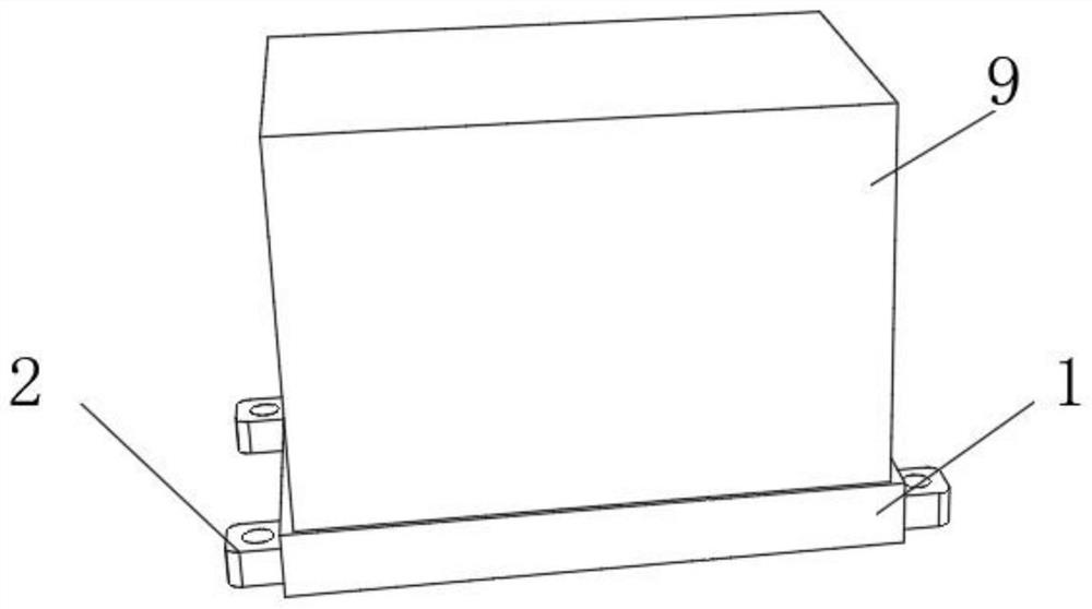
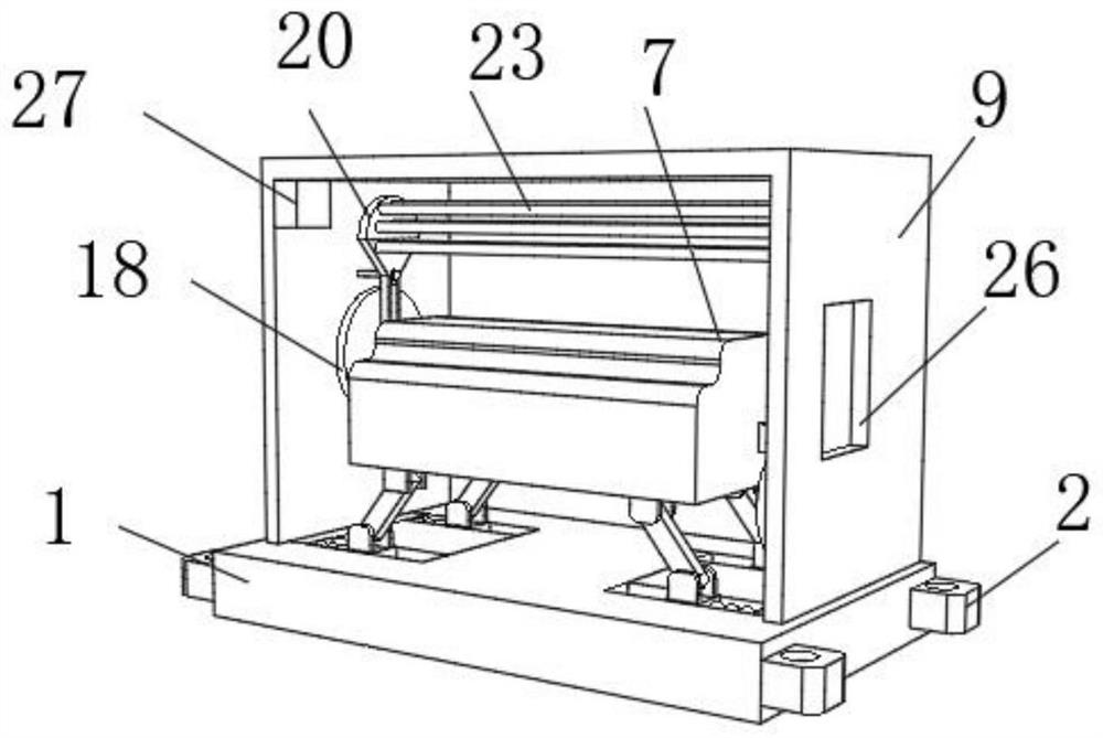
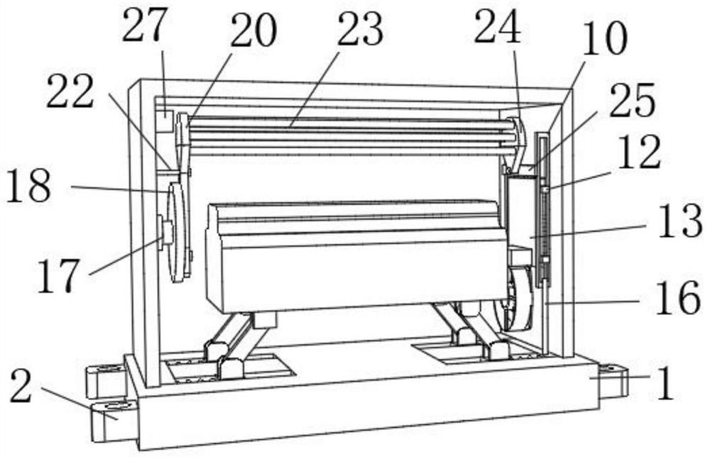
[0027] like Figure 1-7 As shown, the embodiment of the present invention provides a split-type vehicle-mounted inverter with a temperature control function, including a base 1, a protective case 9 is fixedly connected to the top of the base 1, and an inverter body 7 is arranged inside the protective case 9. The right inner wall of the protective case 9 is fixedly connected with two fixed blocks 10, and the inside of the two fixed blocks 10 is provided with a first chute 11, and the inside of the two first chute 11 is slidably connected with a slider 12. A baffle plate 13 is fixedly connected between the inner sides of the two sliders 12, a connecting block 14 is fixedly connected to the inner side of the lower end of the baffle plate 13, a fan 15 is arranged at the lower end of the connecting block 14, and an electric telescopic rod is fixedly connected to the right side of the top of the base 1. 16. The output end of the electric telescopic rod 16 is connected to the lower e...
PUM
 Abstract
Description
Claims
Application Information