Supercharge Your Innovation With Domain-Expert AI Agents!

Automatic rubber tapping machine

A rubber machine and automatic technology, applied in forestry, application, agriculture, etc., can solve the problems of cutting the rubber tree body, breaking the blade, and the blade has no structure to limit the amount of knots, and achieve the effect of avoiding waste and flexible use

Pending Publication Date: 2022-03-01
SHENZHEN JIUZHOU ELECTRIC +1
View PDF0 Cites 0 Cited by
  • Summary
  • Abstract
  • Description
  • Claims
  • Application Information

AI Technical Summary

Problems solved by technology

It uses a fixed motor to connect the moving frame to move on the guide rail and connect the blade frame to move vertically. It is difficult to accurately ensure that the cutting angle and feed rate of the blade remain unchanged, so that the blade is stuck by the trunk when cutting into the bark of the rubber tree. Affect further cutting and tapping operations, and even easily break the blade during operation
[0005] (3) Fixed advance and retreat knife holder structure, unable to fine-tune the advance and angle of the blade
The blade does not have a precise structure to limit the amount of knots, and it cannot guarantee accurate adjustment of cut and depth when different tree diameters are used
At the same time, technical problems such as damage to the blades of the above (1) and (2) and cutting of the rubber tree body are caused.
[0006] (4) The rubber condensed at the old tapping port cannot be recycled, and the bark and glue line will hang on the blade, knife holder or fuselage during re-cutting, causing damage to the blade, knife holder or fuselage, and at the same time causing Waste of glue line and pollute the environment
[0007] To sum up, in the prior art, the cutting operation of the blade in a fixed form appears, and the above-mentioned problems are easy to occur, which has become a technical problem to be solved urgently

Method used


Image

  • Automatic rubber tapping machine
  • Automatic rubber tapping machine
  • Automatic rubber tapping machine

Examples


no. 1 approach

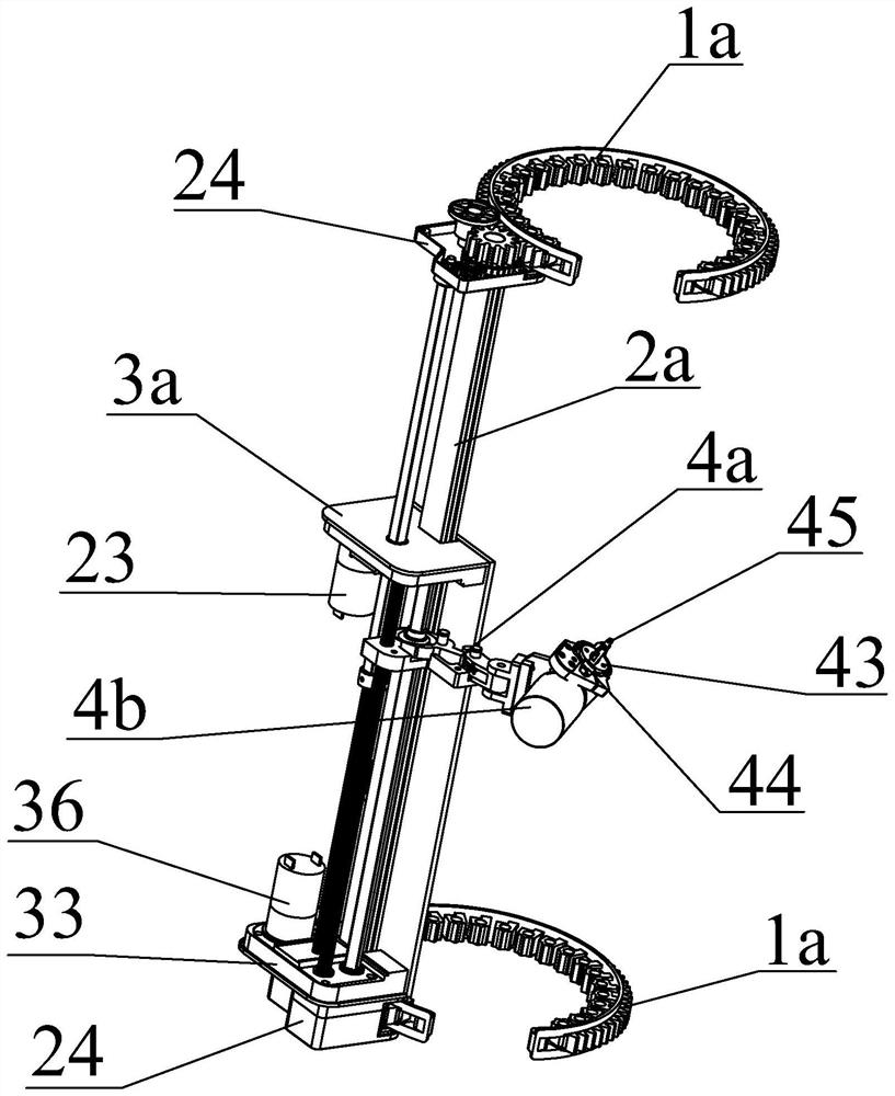
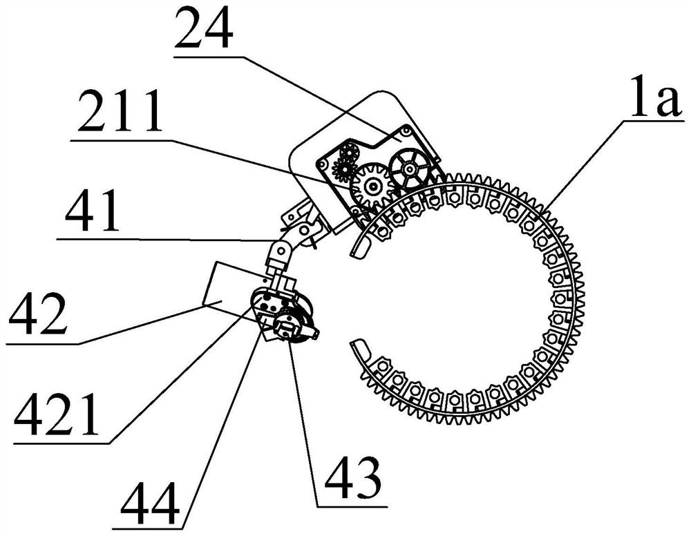
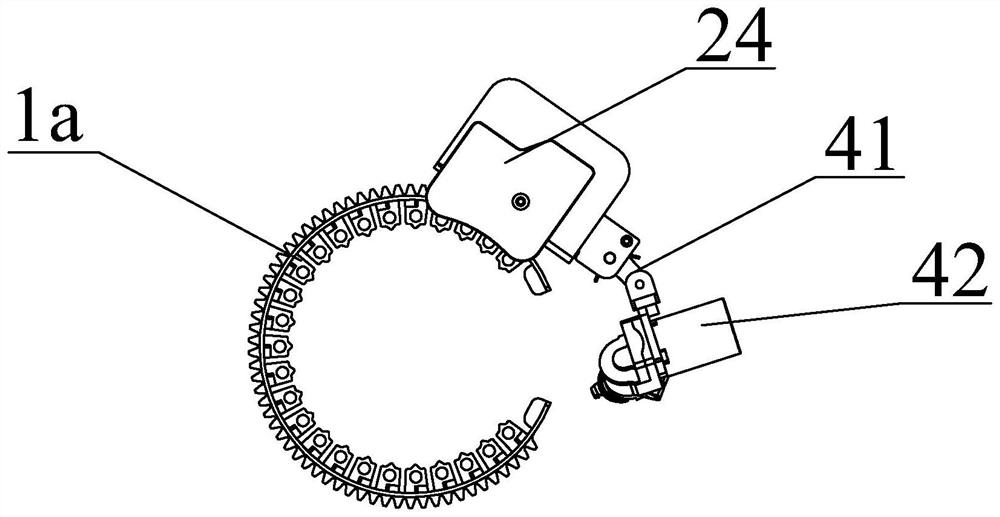
[0046] refer to Figure 1 to Figure 5 As shown, in this embodiment, the cutter module 4a includes a liftable and swingable knife adjustment bracket 41, the electric mechanism 4b includes a rubber tapping motor 42 and a rotary cutter head 43 linked with the rubber tapping motor 42, and the rubber tapping motor 42 is positioned at the adjustment position. On the knife support 41, the rotary cutter 44 is fixed on the rotary cutter head 43.

[0047] The cutting knife module 4 a also includes an arc-shaped positioning ring 422 , through which the cutting amount of the cutting edge of the rotary cutting knife 44 is limited. There are at least two rotary cutters 44 , which are evenly arranged on the edge of the rotary cutter head 43 .

[0048] The rubber tapping motor 42 is provided with an adjustment disc 421, and the positioning ring 422 is positioned on the adjustment disc 421 to adjust its positioning angle and the feed rate of the knife edge.

[0049] Adjustment plate 421 is p...

no. 2 approach

[0053] refer to Figure 1 to Figure 9 As shown, in this embodiment, the outer arc wall of the arc guide rail 1a body is provided with outer ring teeth 11 , the inner arc wall is provided with inner ring teeth 12 , and the arc guide rail 1a is provided with locking connectors 14 .

[0054] An annular channel 13 is provided along the arc-shaped guide rail 1a, and the locking connector 14 is a band, which is inserted in the annular channel 13 . Wherein, the locking connector 14 includes but is not limited to a strap, a cable tie throat hoop, etc., which can be selected and used according to specific situations.

[0055] In this embodiment, the arc-shaped guide rail 1a can be deformed, and can be more conveniently embraced on the tree trunk, wherein it is locked and fixed by the locking connector 14, so that the moving frame 2a can move stably between the upper and lower arc-shaped guide rails 1a . The outer ring teeth 11 and the inner ring teeth 12 have a tooth pattern structur...

no. 3 approach

[0057] refer to Figure 1 to Figure 13 As shown, in this embodiment, the moving frame 2a includes a linear guide rail 21, a linkage rod 22, a drive motor 23 and a walking seat 24 located at both ends of the linear guide rail 21, and the two ends of the linkage rod 22 pass through the travel gear 211 and the arc. The outer ring teeth 11 of the guide rail 1a are meshed and connected, and the driving motor 23 is arranged on the traveling seat 24 or the lifting module 3a to drive the linkage rod 22 to rotate.

[0058]Wherein when the drive motor 23 is located on the travel seat 24, it is directly meshed with the travel gear 211 through a gear structure to drive the travel gear 211 to rotate, and the travel gear 211 walks on the outer ring teeth 11 during rotation to drive the travel seat 24 moves on the arc guide rail 1a. When the drive motor 23 is arranged on the lifting module 3a, the drive motor 23 can be engaged by gears by driving the linkage rod 22 to rotate, and the contro...


PUM


Abstract

The invention discloses an automatic rubber tapping machine which comprises an upper arc-shaped guide rail, a lower arc-shaped guide rail, a moving frame movably arranged between the arc-shaped guide rails and a lifting module arranged on the moving frame, a movable cutting knife module is arranged on the lifting module, and the cutting knife module comprises an electric mechanism and a rotary cutting knife rotationally connected with the electric mechanism. And the electric mechanism controls the rotary cutting knife to rotate and cut. Through the mode, the automatic rubber tapping machine provided by the invention adopts a rotary cutting mode of the rotary cutting knife, and has the advantages that the cutting is stable and rapid, the cutting effect is good, a rubber solution better flows out through the knife edge, the rotary cutting knife cannot be clamped during use, and the stability of cutting operation is kept.

Description

technical field [0001] The invention relates to a rubber tapping device, in particular to an automatic rubber tapping machine. Background technique [0002] In the rubber collection of the rubber tree, the cutting edge of the rubber bark is repeatedly cut obliquely every few days to generate a new knife edge, so that the rubber liquid flows out from the mouth, and the rubber liquid flows into the rubber bottle along the oblique knife edge. The traditional way of manual tapping is to use a hand-held rubber tapping knife or an electric tapping knife to cut the bark, which consumes manpower and material resources and is inefficient. In order to increase the efficiency of rubber collection, the rubber tapping machine of the prior art adopts mechanized operation to improve the efficiency of rubber tapping and reduce the labor intensity of labor. In the prior art, an automatic rubber tapping machine that is fixed on the rubber tree for a period of time is used. The rubber tapping...

Claims


Application Information

Patent Timeline
IPC IPC(8): A01G23/10A01G23/12
CPCA01G23/10A01G23/12
Inventor 谭军张金明朱其厚
Owner SHENZHEN JIUZHOU ELECTRIC
Features
  • R&D
  • Intellectual Property
  • Life Sciences
  • Materials
  • Tech Scout
  • Unparalleled Data Quality
  • Higher Quality Content
  • 60% Fewer Hallucinations
Learn More