
Rehabilitation exercise device for orthopedics department

An exercise device and orthopedic rehabilitation technology, applied in sports accessories, muscle training equipment, gymnastics equipment, etc., can solve the problems of occupying too much space and single exercise device

Pending Publication Date: 2022-03-01
周爽
View PDF6 Cites 0 Cited by
  • Summary
  • Abstract
  • Description
  • Claims
  • Application Information

AI Technical Summary

Problems solved by technology

[0003] During orthopedic treatment, it is necessary to carry out rehabilitation treatment for the patient so as to prevent long-term inactivity and affect the patient's normal activities and even affect the nerve and blood circulation. However, the currently used orthopedic rehabilitation devices exercise the legs or arms. Currently, The exercise devices used are relatively single, and only one part can be exercised, and too much equipment tends to take up too much space

Method used


Image

  • Rehabilitation exercise device for orthopedics department
  • Rehabilitation exercise device for orthopedics department
  • Rehabilitation exercise device for orthopedics department

Examples


Embodiment 1

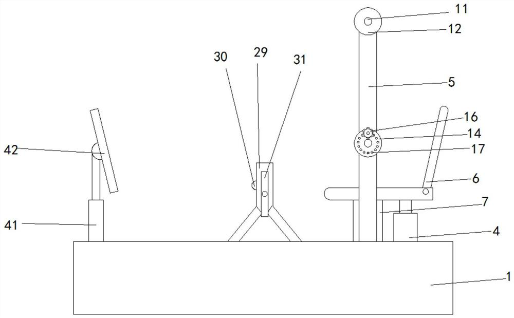
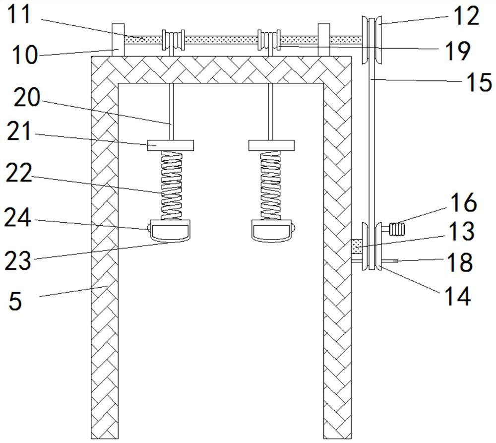
[0031] Embodiment one, such as figure 1As shown in - 8, an orthopedic rehabilitation exercise device according to an embodiment of the present invention includes a base 1, a movable groove 1 2 and a movable groove 2 3 are provided on the top of the base 1, and a hydraulic cylinder is provided on the top side of the base 1 4. The top output end of the hydraulic cylinder 4 is provided with a seat 6, and the bottom side of the seat 6 is provided with a support column 7, and the bottom end of the support column 7 penetrates into the movable groove 2 and supports Mechanism connection, the support structure includes a chute 8 located on the inner wall of the movable groove 2, and both sides of the bottom end of the support column 7 penetrate into the chute 8, and the chute 1 The inside of 8 is provided with spring one 9, and the top of described spring one 9 is squeezed together with the bottom of described support column 7, and described base 1 top and is positioned at the outside ...

Embodiment 2

[0032] Embodiment 2, the limiting mechanism includes several through holes 17 located on the outer surface of the pulley 2 14, the through holes 17 are provided with limiting rods 18, and the outer surface of the frame 5 is provided with the limiting rods. A limit slot matched with the end of the position bar 18, the inside of the position limit slot is provided with a magnet, the position limit bar 18 is made of iron metal material, the outer limit block 32, the middle limit block 33 And the outer surfaces of the three inner limit blocks 34 are provided with gaskets that match the tripod 31, the support column 7, the outer limit block 32, the middle limit block 33 and All four of the inner limiting blocks 34 are T-shaped structures. It is not difficult to see from the above design that the design of the gasket prevents external dust from entering the tripod 31 .

Embodiment 3

[0033] Embodiment 3, the inside of the handle 23 is provided with several bumps, finger grooves are formed between two adjacent bumps, anti-slip lines are provided in the finger grooves, the spring one 9, the spring two 22 The ends of the spring three 36 and the spring four 37 are provided with spring washers, the other end of the screw rod 39 away from the servo motor 40 is provided with a shaft support seat, and the dirt handle 16 The outer surface is provided with a non-slip pad, and the outer surface of the protective pad is provided with several sweat-guiding grooves, and the outer surface of the protective pad and the area between two adjacent sweat-guiding grooves are provided with anti-slip embossed lines. The inner surface of the frame 5 is provided with a scale line, the top of the frame 5 is provided with a hole matched with the traction rope 20, the inside of the base 1 is provided with a controller, a storage battery, the hydraulic cylinder 4, the The first speed ...


PUM


Abstract

The orthopedic rehabilitation exercise device comprises a base, a first movable groove and a second movable groove are formed in the top of the base, a hydraulic cylinder is arranged on one side of the top of the base, a seat is arranged at the output end of the top of the hydraulic cylinder, and a supporting column is arranged on one side of the bottom of the seat; the bottom end of the supporting column penetrates into the first movable groove to be connected with a supporting mechanism, the supporting structure comprises a first sliding groove formed in the inner wall of the first movable groove, the two sides of the bottom end of the supporting column penetrate into the first sliding groove, and a first spring is arranged in the first sliding groove. The top end of the first spring and the bottom of the supporting column are extruded together, and a frame is arranged at the position, located on the outer side of the first movable groove, of the top of the base. The arm exerciser has the beneficial effects that when a patient exercises arms, firstly, the height of the seat is adjusted through the hydraulic cylinder according to the height of the patient, and after the height is adjusted, the descending length of the traction rope is adjusted according to the length of the arms of the patient.

Description

technical field [0001] The invention relates to the technical field of medical equipment, in particular to an orthopedic rehabilitation exercise device. Background technique [0002] Orthopedics is one of the most common departments in major hospitals. It mainly studies the anatomy, physiology and pathology of the musculoskeletal system, and uses drugs, surgery and physical methods to maintain and develop the normal form and function of this system. , the spectrum of orthopedic injuries has changed significantly, for example, bone and joint tuberculosis, osteomyelitis, polio and other diseases have decreased significantly, trauma caused by traffic accidents has increased significantly, and the spectrum of orthopedic injuries has changed, which requires orthopedics to keep pace with the times in. [0003] During orthopedic treatment, it is necessary to carry out rehabilitation treatment for the patient so as to prevent long-term inactivity and affect the patient's normal act...

Claims


Application Information

Patent Timeline
IPC IPC(8): A63B23/12A63B21/05A63B21/055A63B23/035A63B23/04A63B71/06
CPCA63B23/12A63B21/055A63B21/05A63B23/04A63B71/0619A63B23/03575A63B2225/093A63B2208/0233
Inventor 不公告发明人
Owner 周爽
Learn More