Thermal stress eliminating structure

A technology for thermal stress and load-bearing components, which is applied in the direction of textiles and papermaking, rope-making auxiliary devices, textile cables, etc., and can solve problems such as the difficulty of realizing lightweight design concepts, large component stress, material selection and complex structures, etc.

Active Publication Date: 2022-03-01
CRRC CHANGCHUN RAILWAY VEHICLES CO LTD
View PDF12 Cites 0 Cited by
  • Summary
  • Abstract
  • Description
  • Claims
  • Application Information

AI Technical Summary

Problems solved by technology

[0002] In the structural design of low-temperature service components, it usually involves the working condition that the temperature drops from normal temperature to low temperature. Due to the different linear expansion coefficients of different materials, and the large difference in shrinkage deformation between the normal temperature end and the low temperature end, there will be relatively large internal deformation of the component. Large stress, which in turn leads to complex material selection and structure in the structural design of components, and it is difficult to realize the lightweight design concept, and even some parts may be damaged due to local stress concentration

Method used


Image

  • Thermal stress eliminating structure
  • Thermal stress eliminating structure
  • Thermal stress eliminating structure

Examples


Embodiment Construction

[0031] The invention discloses a thermal stress relief structure, which eliminates the internal stress of low-temperature service components when the working temperature changes.

[0032] The technical solutions in the embodiments of the present invention will be clearly and completely described below in conjunction with the accompanying drawings in the embodiments of the present invention. Obviously, the described embodiments are only some, not all, embodiments of the present invention. Based on the embodiments of the present invention, all other embodiments obtained by persons of ordinary skill in the art without making creative efforts fall within the protection scope of the present invention.

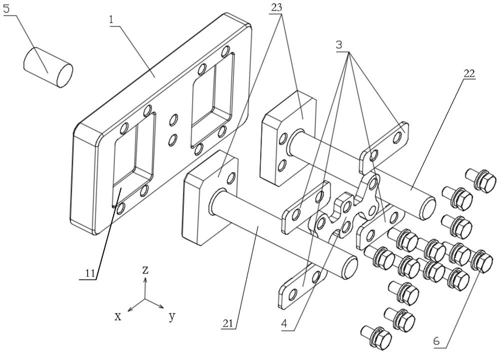
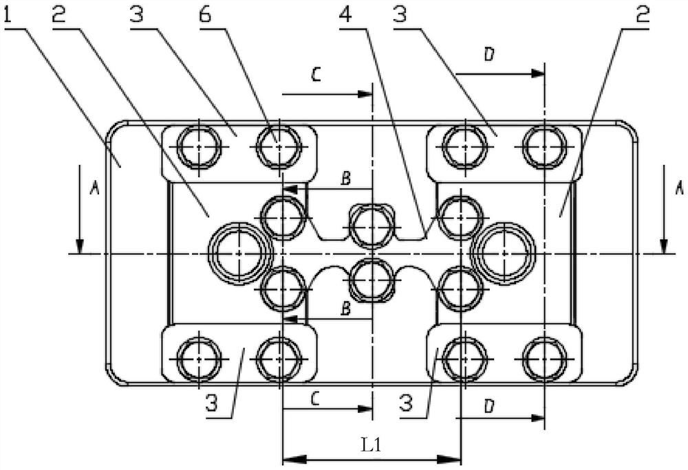
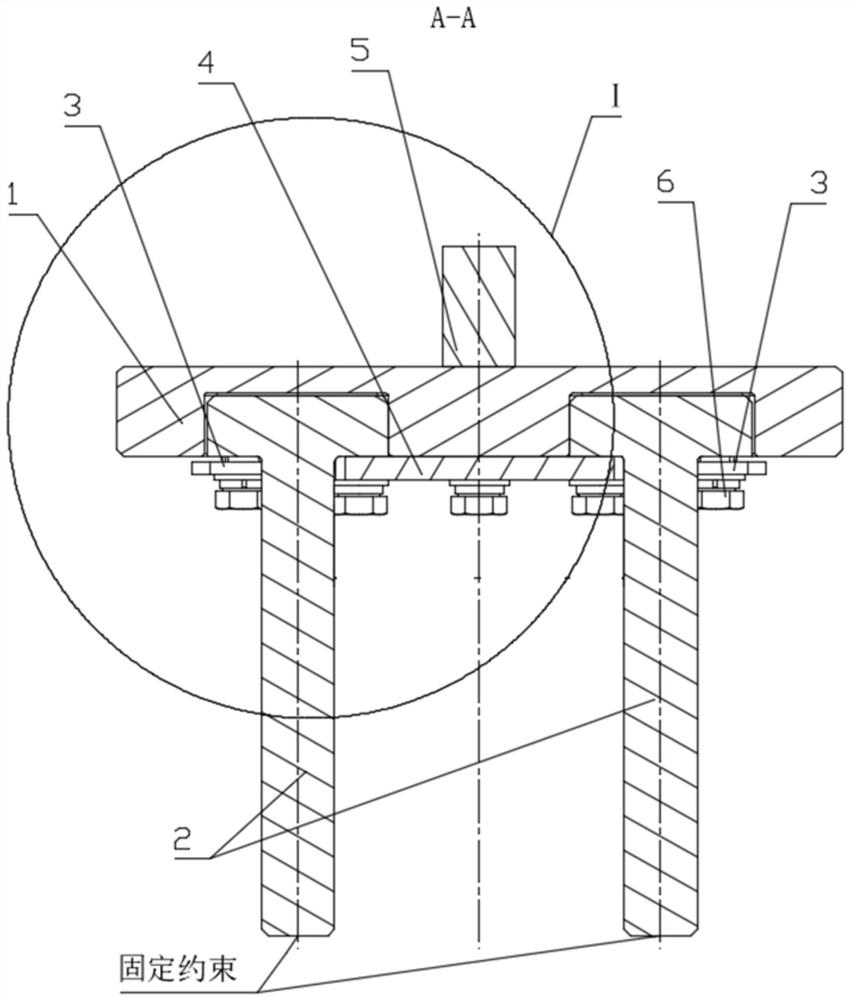
[0033] Such as Figure 1-Figure 6 as shown, figure 1 An exploded view of the thermal stress relief structure provided for the present invention; figure 2 The front view of the thermal stress relief structure provided by the present invention; image 3 for figure 2 A-A directio...


PUM


Abstract

The invention provides a thermal stress eliminating structure which is characterized in that a shrinkage gap is formed between an installation sinking groove and a T-shaped connector under the normal temperature condition, the shrinkage rate of a main pressing plate is set to be smaller than that of a main shrinkage body, the shrinkage amount of the main shrinkage body is larger than that of the main pressing plate under the low temperature condition, and after the main shrinkage body shrinks, the two installation sinking grooves on the main shrinkage body are close to each other; the relative displacement amount of the first main bearing component and the second main bearing component is smaller than the shrinkage amount of the main shrinkage body due to supporting of the main pressing plate, and a shrinkage gap for sliding of the T-shaped connector is reserved in the shrinkage direction of the main shrinkage body, so that the mounting sinking groove is filled and pressed in the sliding direction of the T-shaped connector, and the T-shaped connector is prevented from being damaged. Stress transmitted to the first main bearing component and the second main bearing component by synchronous contraction of the two components is avoided, stress concentration is avoided, and the safety of the supporting structure is guaranteed.

Description

technical field [0001] The invention relates to the technical field of material stress analysis, and more specifically relates to a thermal stress relief structure. Background technique [0002] In the structural design of low-temperature service components, it usually involves the working condition that the temperature drops from normal temperature to low temperature. Due to the different linear expansion coefficients of different materials, and the large difference in shrinkage deformation between the normal temperature end and the low temperature end, there will be relatively large internal deformation of the component. Large stress, which in turn leads to complex material selection and structure in structural design of components, difficulty in realizing lightweight design concepts, and even damage to some components due to local stress concentration. [0003] Therefore, how to eliminate the internal stress of low-temperature service components when the operating tempera...

Claims


Application Information

Patent Timeline
Patent Type & Authority Applications(China)
IPC IPC(8): D07B7/16
CPCD07B7/16Y02E60/10
Inventor 胡浩李凯刘建宏乔伟超
Owner CRRC CHANGCHUN RAILWAY VEHICLES CO LTD
Why Eureka
Try Eureka