A gas pipeline large displacement protection device

A gas pipeline and protective device technology, which is applied in the direction of pipeline protection, pipeline damage/abrasion prevention, pipes/pipe joints/pipe fittings, etc., can solve problems such as gas pipeline breakage and gas leakage, and achieve the effect of protecting metal bellows

Active Publication Date: 2021-08-31
INST OF ENG MECHANICS CHINA EARTHQUAKE ADMINISTRATION
View PDF8 Cites 0 Cited by
  • Summary
  • Abstract
  • Description
  • Claims
  • Application Information

AI Technical Summary

Problems solved by technology

[0003] The present invention intends to provide a gas pipeline large-displacement protection device to solve the problem that the gas pipeline is broken due to large displacement caused by an earthquake, resulting in gas leakage

Method used


Image

  • A gas pipeline large displacement protection device
  • A gas pipeline large displacement protection device
  • A gas pipeline large displacement protection device

Examples


Embodiment

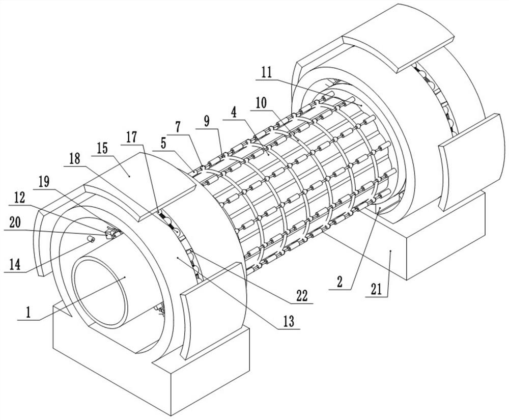
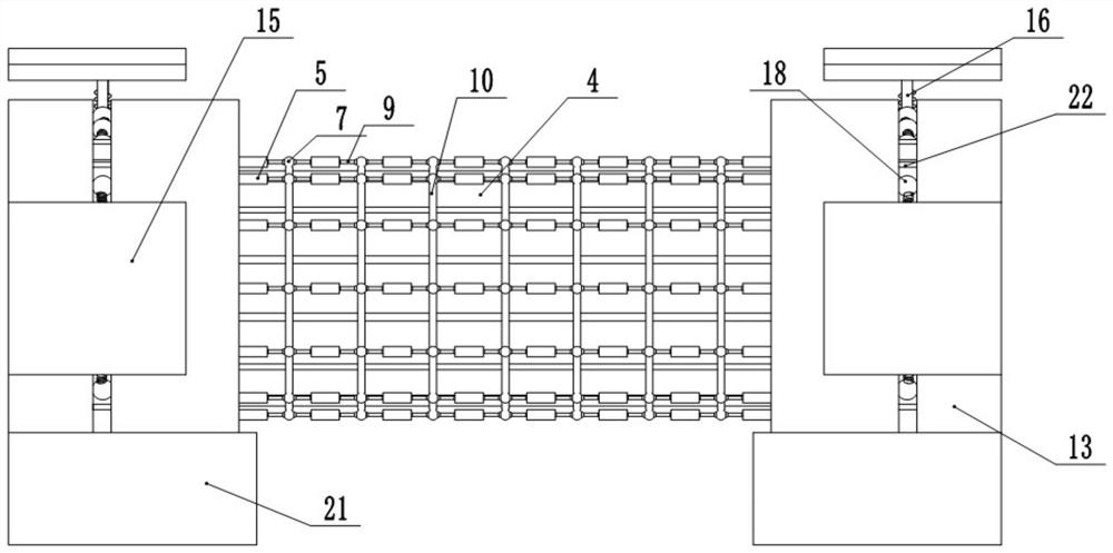
[0024] Such as figure 1 , figure 2 , image 3 , Figure 4 , Figure 5 and Figure 6 The large-displacement protection device for gas pipelines shown includes a metal bellows 3 located between adjacent gas pipelines 1. Both ends of the metal bellows 3 are welded with flanges 11 connected to the gas pipeline 1. Between the flanges 11, there are twelve sets of protective structures distributed in a circular array. The protective structure includes several connecting columns 5, and both ends of the connecting columns 5 are provided with elliptical chambers, and buffer balls are slidingly connected in the chambers. 6, and a spring is welded between the inner wall of the chamber and the buffer ball 6; a connecting ball 7 is arranged between the adjacent connecting columns 5, and both ends of the connecting ball 7 are provided with an oval buffer chamber, and a deflection chamber is provided in the buffer chamber The ball 8, the deflection ball 8 and the buffer cavity are fixed...

specific Embodiment approach

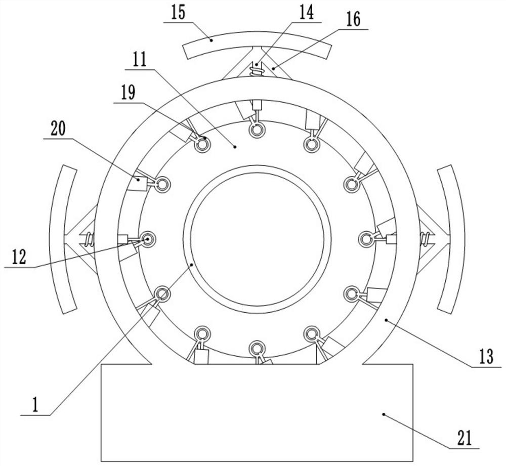
[0025] When an earthquake occurs, after the shock sensor senses the shock, the shock signal is transmitted to the PLC controller, and the PLC controller judges logically, if the magnitude of the shock does not cause a large displacement of the gas pipeline 1, then the PLC controls the telescopic cylinder 20 to not start; One or more shock-absorbing plates 15 are extruded during the rock deformation, so that the shock-absorbing plates 15 drive the shock-absorbing rods 14 to slide toward the arc-shaped plates 13, and the springs fixed between the shock-absorbing rods 14 and the arc-shaped plates 13 perform the first Secondary cushioning and shock absorption; while the shock absorbing rod 14 slides, it drives the support rods 16 on both sides, thereby pushing the ball 17 to slide in the chute, and the sphere 17 pushes the ball 18 chute, and passes through the ball 17, the ball 18 and the chute. The friction between them performs energy dissipation and shock absorption.

[0026] T...


PUM


Abstract

The invention relates to the technical field of gas pipelines, and specifically discloses a large-displacement protection device for gas pipelines, which includes metal bellows located between adjacent gas pipelines, and flanges connected to the gas pipelines are fixed at both ends of the metal bellows , there are several groups of protection structures distributed in a circular array between adjacent flanges. The protection structure includes several sections of protection columns. Both ends of the protection columns are provided with elliptical chambers, and buffer balls are slidingly connected in the chambers. In addition, a spring is fixed between the inner wall of the chamber and the buffer ball; connecting balls are arranged between adjacent protective columns, and both ends of the connecting ball are provided with an elliptical buffer chamber, and a deflection ball is arranged in the buffer chamber, and the deflection ball and the buffer A spring is fixed in the cavity, and a connecting rod is fixed between the deflection ball and the adjacent buffer ball; the invention aims to solve the problem of gas leakage caused by gas pipeline rupture due to large displacement caused by earthquakes.

Description

technical field [0001] The invention relates to the technical field of gas pipelines, and specifically discloses a large displacement protection device for gas pipelines. Background technique [0002] Gas pipeline is a pipeline specially used to transport gas. It has the characteristics of convenient connection, convenient use and long service life. Due to the generalization of gas and the diversity of gas applications, gas pipelines are fully utilized. Earthquakes are the greatest threat to the safety of gas pipeline systems. Once the gas pipeline is damaged in an earthquake, it will bring huge national economic losses and casualties, and difficulties in energy and material supply in the earthquake area, which will have a huge impact on earthquake emergency response and post-earthquake recovery work. During an earthquake, the large displacement of the rock and soil mass is the most important factor for the damage of the pipeline system. The large displacement of the rock a...

Claims


Application Information

Patent Timeline
Patent Type & Authority Patents(China)
IPC IPC(8): F16L27/11F16L57/02F16F15/00F16F15/02F16F15/04F16F15/067
CPCF16F15/002F16F15/02F16F15/021F16F15/046F16F15/067F16F2222/04F16F2238/026F16L27/11F16L57/02
Inventor 孙得璋何先龙郭恩栋刘志斌张昊宇
Owner INST OF ENG MECHANICS CHINA EARTHQUAKE ADMINISTRATION
Why Eureka
Try Eureka