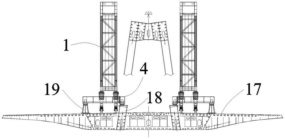
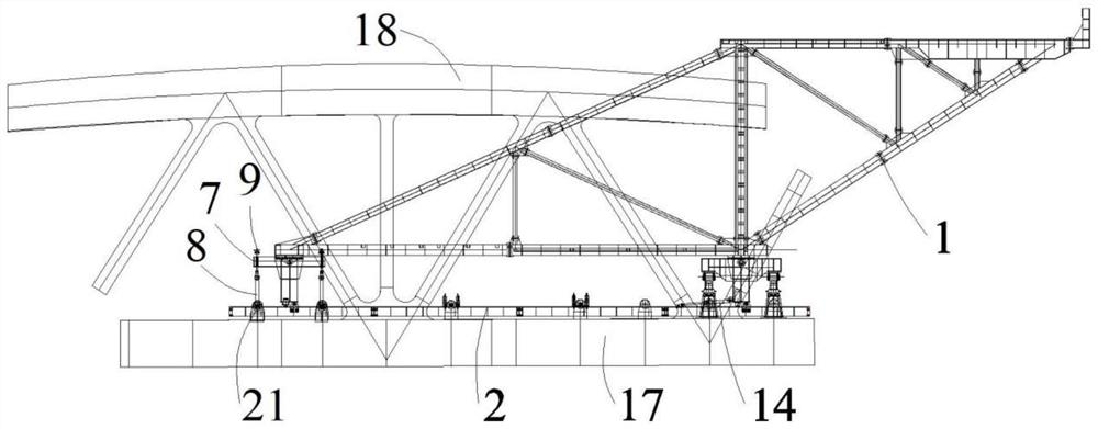
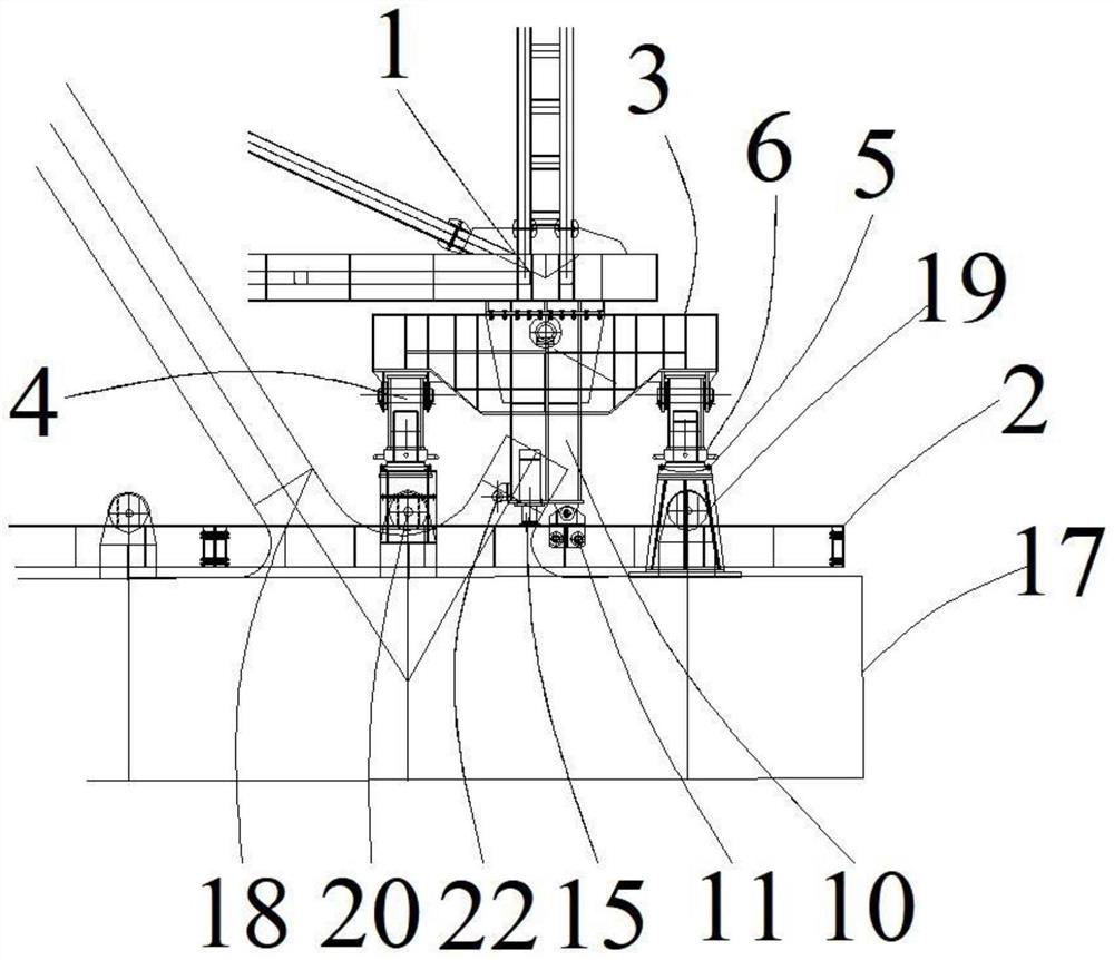
Steel box truss combined bridge deck crane supporting and anchoring system and walking method

A combined bridge deck and crane technology, which is applied to bridges, bridge construction, erection/assembly of bridges, etc., can solve the problems that the crane anchor system cannot be used and is not feasible, so as to achieve simple and convenient installation and adjustment methods and improve construction efficiency. Efficiency, effect of anchoring structure stability

Pending Publication Date: 2022-03-01
CHINA RAILWAY CONSTR BRIDGE ENG BUREAU GRP +2
View PDF1 Cites 0 Cited by
  • Summary
  • Abstract
  • Description
  • Claims
  • Application Information

AI Technical Summary

Problems solved by technology

However, this walking mechanism only considers the walking of the bridge deck crane. In fact, during the use of the bridge deck crane, support and anchoring are an important part of the entire use process, but the walking mechanism is only buckled by reverse buckle The overturning of the bridge deck crane is limited on the track, and the entire support is completely based on the track, that is to say, the bridge deck crane introduced in the modified patent is completely supported on the track, which is more suitable for light and small bridge deck cranes, but For large and heavy deck cranes, it is obviously not feasible
In order to reduce the weight of the steel box girder of the steel box truss composite bridge of thousands of tons, the internal webs are all thin, which cannot provide enough support and anchoring structure for the crane. Therefore, the traditional crane cannot be used. Machine anchor system

Method used


Image

  • Steel box truss combined bridge deck crane supporting and anchoring system and walking method
  • Steel box truss combined bridge deck crane supporting and anchoring system and walking method
  • Steel box truss combined bridge deck crane supporting and anchoring system and walking method

Examples


Embodiment Construction

[0057] Embodiments of the present invention are described in detail below, wherein the same or similar reference numerals represent the same or similar elements or elements having the same or similar functions. The embodiments described below by referring to the figures are exemplary and are intended to explain the present invention and should not be construed as limiting the present invention.

[0058] In describing the present invention, it should be understood that the terms "longitudinal", "transverse", "length", "width", "thickness", "upper", "lower", "front", "rear", " The orientation or positional relationship indicated by "left", "right", "vertical", "horizontal", "top", "bottom", "inner" and "outer" are based on the orientation or positional relationship shown in the drawings, and only It is for the convenience of describing the present invention and simplifying the description, but does not indicate or imply that the referred device or element must have a specific or...


PUM


Abstract

The invention relates to the technical field of building construction, in particular to a steel box truss combined bridge deck crane supporting and anchoring system and a walking method. Comprising a bridge deck crane support and a track laid on a steel box girder in the longitudinal direction, the bridge deck crane support is provided with a front end supporting structure, and the front end supporting structure is located at the front end of the bridge deck crane support and supported on the steel box girder and/or a steel truss when the bridge deck crane is in an operation state; the rear end supporting structure is positioned at the rear end of the bridge deck crane bracket and is anchored on the steel box girder when the bridge deck crane is in a working state; the walking structure is slidably connected to the track and used for driving the deck crane support to advance along the track; and the jacking structure is used for driving the bridge deck crane bracket to vertically move before the bridge deck crane enters the walking state, so that the walking structure is supported on the track. The supporting and anchoring system is simple in structure and convenient to operate, construction efficiency and safety are greatly improved, damage to the steel box girder and the track is avoided, and the supporting and anchoring system has great popularization value.

Description

technical field [0001] The invention relates to the technical field of building construction, in particular to a steel box truss composite deck crane anchor system and a walking method. Background technique [0002] During the bridge hoisting operation, the crane needs to adapt to the hoisting and walking conditions for support and anchoring (also known as the anchor system). The traditional anchor system requires independent hoisting mechanical support, walking mechanical support and hoisting mechanical anchorage. Such as the patent No. "CN206941419U", a Chinese utility model patent titled "A Walking Mechanism of a Bridge Deck Crane", which introduces a walking mechanism of a Bridge Deck Crane, including: at least one set of driving devices, which It is arranged at the front fulcrum crossbeam of the bridge deck crane to drive the bridge deck crane to move; the traveling wheel is arranged under the rear anchor beam of the bridge deck crane, and is fixed to the rear anchor c...

Claims


Application Information

Patent Timeline
Patent Type & Authority Applications(China)
IPC IPC(8): E01D21/00
CPCE01D21/00
Inventor 施向华易佳佳
Owner CHINA RAILWAY CONSTR BRIDGE ENG BUREAU GRP
Why Eureka
Try Eureka