Eureka AIR delivers breakthrough ideas for toughest innovation challenges, trusted by R&D personnel around the world.

Reinforced seepage and drainage water collecting pipe and using method thereof

A technology for seepage and drainage and collection pipes, applied in the field of seepage and drainage pipes, can solve the problems of easily damaged waterproof layer, low load-bearing capacity of U-shaped structure, damage to filter cloth, etc., and achieves the effect of increasing the contact area and facilitating integrated injection molding.

Pending Publication Date: 2022-03-01
兴合环保科技(山东)有限公司
View PDF1 Cites 0 Cited by
  • Summary
  • Abstract
  • Description
  • Claims
  • Application Information

AI Technical Summary

Problems solved by technology

[0003] Due to the large height difference between the seepage drainage tank and the filter cloth, the filter cloth above the water inlet on the side of the attached soil will collapse downward under the gravity of the covering soil, which will easily cause damage to the filter cloth and lead to blockage of the water inlet. The notification number is CN211421240U The utility model patent discloses a siphon rainwater collection and drainage tank applied to sponge cities. A baffle is set above the water inlet to support the filter cloth. However, in order to demould the mold under the baffle, the drainage tank only It can be a U-shaped structure with an opening at the bottom, so that the mold at the water inlet under the baffle can be disassembled through the bottom
[0004] The U-shaped structure has a small contact area with the waterproof layer, which is easy to damage the waterproof layer, and the inverted U-shaped structure has a low load-bearing capacity and is easily crushed by the covering soil.

Method used


Image

  • Reinforced seepage and drainage water collecting pipe and using method thereof
  • Reinforced seepage and drainage water collecting pipe and using method thereof
  • Reinforced seepage and drainage water collecting pipe and using method thereof

Examples


Embodiment Construction

[0035] In order to clearly illustrate the technical features of the solution, the solution will be described below through specific implementation modes.

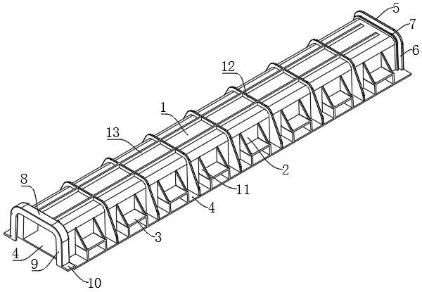
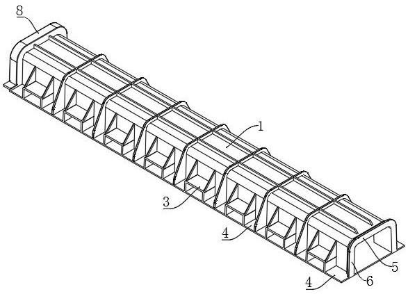
[0036] like Figure 1~9 As shown, a reinforced seepage drainage collection pipe of the present invention is integrally injection-molded, including a horizontally arranged pipe body, the pipe body includes a top plate 1, a bottom plate 4 and vertical plates 2 extending downward from both sides of the top plate 1, The lower end of the vertical plate 2 is affixed to the upper surface of the bottom plate 4 , so that the top plate 1 , the bottom plate 4 and the vertical plate 2 form a pipe body with a rectangular cross-section.

[0037] The bottom plate 4 extends horizontally to the outside of the vertical plate 2 , thereby increasing the area of ​​the bottom plate 4 .

[0038] The vertical board 2 is connected with a plurality of water inlet pipes 3 extending to the outside of the pipe body, the water inlet pipes 3 on the vert...


PUM


Abstract

The invention relates to a reinforced seepage and drainage water collecting pipe and a using method thereof.The reinforced seepage and drainage water collecting pipe comprises a transversely-arranged pipe body, the pipe body comprises a top plate, a bottom plate and vertical plates extending downwards from the two sides of the top plate, the lower ends of the vertical plates are fixedly connected with the upper end face of the bottom plate, and the vertical plates communicate with a plurality of water inlet pipes extending towards the outer side of the pipe body; the lower end face of the water inlet pipe is flush with the bottom face of the bottom plate, the section of an inner hole of the end, close to the pipe body, of the water inlet pipe is equal to or smaller than the section of an inner hole of the end, away from the pipe body, of the water inlet pipe, vertical supporting rib plates are fixedly connected between the upper end face of the water inlet pipe and the vertical plate, and the upper end faces of the multiple supporting rib plates form a supporting plane. The pipe body is transversely placed on the waterproof layer, the contact area of the pipe body and the waterproof layer is increased, water of the drainage plate flows into the pipe body through the water inlet pipe on the side face, the filter cloth is supported through the supporting plane formed by the upper end faces of the multiple supporting rib plates, and the waterproof layer and the filter cloth can be effectively protected; and integral injection molding is facilitated.

Description

technical field [0001] The invention relates to the field of seepage and drainage pipes, in particular to a reinforced seepage and drainage collection pipe and a method for using the same. Background technique [0002] When collecting rainwater on the roof of a building, a waterproof layer is usually laid on the building, garage or road first, and then a drainage board is laid on the waterproof layer. A layer of filter cloth is laid on the top of the filter cloth, and green soil is covered on the top of the filter cloth. The rainwater passes through the filter cloth and enters the drainage board, then flows into the infiltration and drainage groove through the water inlets on both sides of the drainage groove, and finally enters from the infiltration and drainage groove. Cistern. [0003] Due to the large height difference between the seepage drainage tank and the filter cloth, the filter cloth above the water inlet on the side of the attached soil will collapse downward un...

Claims


Application Information

Patent Timeline
IPC IPC(8): E04D13/04E03B3/02
CPCE04D13/04E04D13/0445E03B3/02Y02A20/108
Inventor 邵明涛张辉
Owner 兴合环保科技(山东)有限公司
Why Eureka
Eureka Blog
Learn More