
Silencing device

A technology of muffler device and muffler chamber, applied in muffler device, exhaust device, engine components, etc., can solve problems such as poor stability

Pending Publication Date: 2022-03-01
中科灵动航空科技成都有限公司
View PDF0 Cites 0 Cited by
  • Summary
  • Abstract
  • Description
  • Claims
  • Application Information

AI Technical Summary

Problems solved by technology

[0006] 3. Most of the existing noise reduction devices are only fixed by a separate external fixing piece, and the stability is poor

Method used


Image

  • Silencing device
  • Silencing device
  • Silencing device

Examples


Embodiment 1

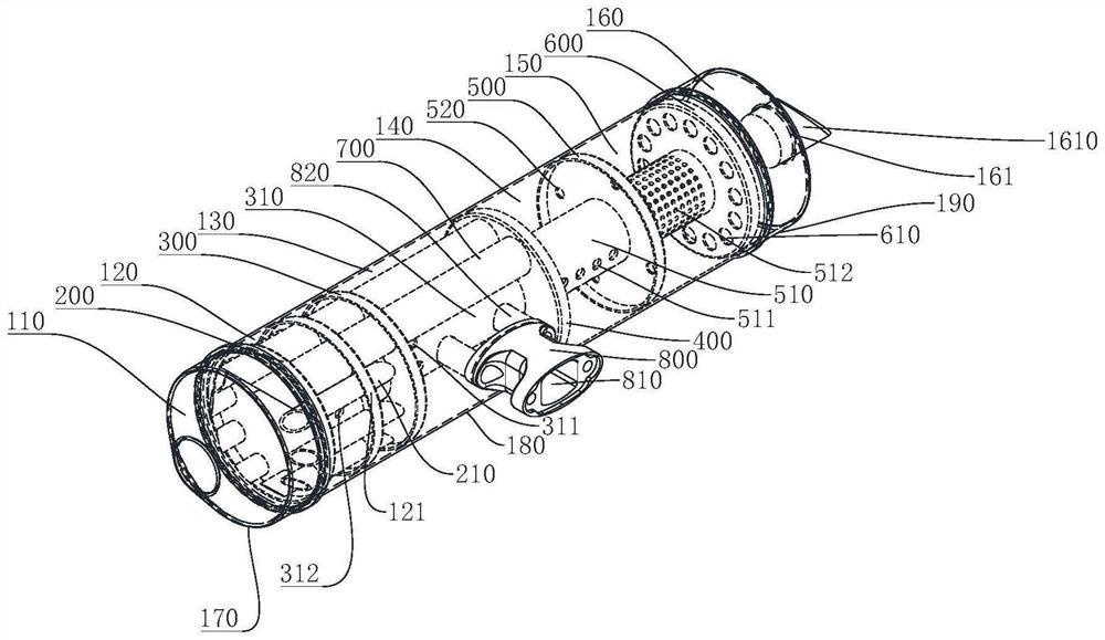
[0042] see Figure 1 to Figure 2 and Figure 5 to Figure 7 . What this embodiment describes is a noise reduction device, which includes an outer shell, and a first partition 200, a second partition 300, a third partition 400, a fourth The baffle 500 and the fifth baffle 600 divide the outer shell into the first anechoic chamber 110, the second anechoic chamber 120, the third anechoic chamber 130, the fourth anechoic chamber 140, the fifth anechoic chamber 150 and the sixth anechoic chamber 160, An air inlet 131 is provided on the outer shell of the third anechoic chamber 130 , and a first ventilation pipe 310 is provided on the second partition 300 , and one end of the first ventilation pipe 310 is installed on the first partition 200 , the other end of the first air pipe 310 is installed on the third partition 400, and the first air pipe 310 located in the third anechoic chamber 130 is provided with a plurality of first air inlet holes 311, located in the second anechoic ch...

Embodiment 2

[0053] see Figure 3 to Figure 7 . What this embodiment describes is a noise reduction device, which includes an outer shell, and a first partition 200, a second partition 300, a third partition 400, a fourth The clapboard 500 and the fifth clapboard 600 divide the outer shell into the first anechoic chamber, the second anechoic chamber, the third anechoic chamber 130, the fourth anechoic chamber 140, the fifth anechoic chamber 150 and the sixth anechoic chamber 160, located in the The outer casing of the third anechoic chamber 130 is provided with an air inlet 131, and the second partition 300 is provided with a first ventilation pipe 310, and one end of the first ventilation pipe 310 is installed on the first partition 200, and the second The other end of a ventilation pipe 310 is installed on the third partition 400, and the first ventilation pipe 310 located in the third anechoic chamber 130 is provided with a plurality of first air inlets 311, and the first aeration hole...


PUM


Abstract

The invention discloses a silencing device, and belongs to the technical field of silencers. The invention aims to process and reduce noise generated by an engine and reduce noise pollution. According to the technical scheme, the silencing device comprises an outer shell, and a first partition plate, a second partition plate, a third partition plate, a fourth partition plate and a fifth partition plate are sequentially arranged between one end and the other end in the outer shell to divide the interior of the outer shell into a first silencing chamber, a second silencing chamber, a third silencing chamber, a fourth silencing chamber, a fifth silencing chamber and a sixth silencing chamber; an air inlet is formed in the outer shell of the third anechoic chamber, and an air outlet is formed in the outer shell of the sixth anechoic chamber.

Description

technical field [0001] The invention belongs to the technical field of noise reduction devices, and relates to a noise reduction device. Background technique [0002] An engine is a machine that can convert other forms of energy into mechanical energy, and is a mechanical device that generates power. The sound intensity produced by the engine when it is working is very loud, and the sound directly transmitted from the engine body and its main accessories to the space belongs to the engine noise. Noise is a by-product of industrial society, and together with air pollution and water pollution, it is considered to be the three major public hazards in the world today. Noise pollution is formed when noise has adverse effects on people and the surrounding environment. Compared with the other two public hazards, noise has the widest influence, the most direct feeling, and the most people's feedback. [0003] In the course of realizing the present invention, the inventor finds th...

Claims


Application Information

Patent Timeline
IPC IPC(8): F01N1/08F01N3/021F01N3/033F01N13/00F01N13/18
CPCF01N1/082F01N1/089F01N3/021F01N3/0335F01N13/007F01N13/18
Inventor 张代智梁虎叶祖峰谭虎
Owner 中科灵动航空科技成都有限公司
Learn More