
Check valve and novel fuel cell stack using same

A check valve and check technology, applied in the field of new fuel cell stacks, can solve the problems of obvious pressure drop, small check valve flow, large flow resistance, etc., and achieve the effect of small flow resistance

Pending Publication Date: 2022-03-01
张家港富瑞阀门有限公司
View PDF1 Cites 0 Cited by
  • Summary
  • Abstract
  • Description
  • Claims
  • Application Information

AI Technical Summary

Problems solved by technology

[0005] The purpose of this application is to provide a check valve and a new fuel cell stack using the check valve to solve the problems of small flow rate, large flow resistance and obvious pressure drop of the check valve proposed in the above background technology

Method used


Image

  • Check valve and novel fuel cell stack using same
  • Check valve and novel fuel cell stack using same
  • Check valve and novel fuel cell stack using same

Examples


Embodiment 1

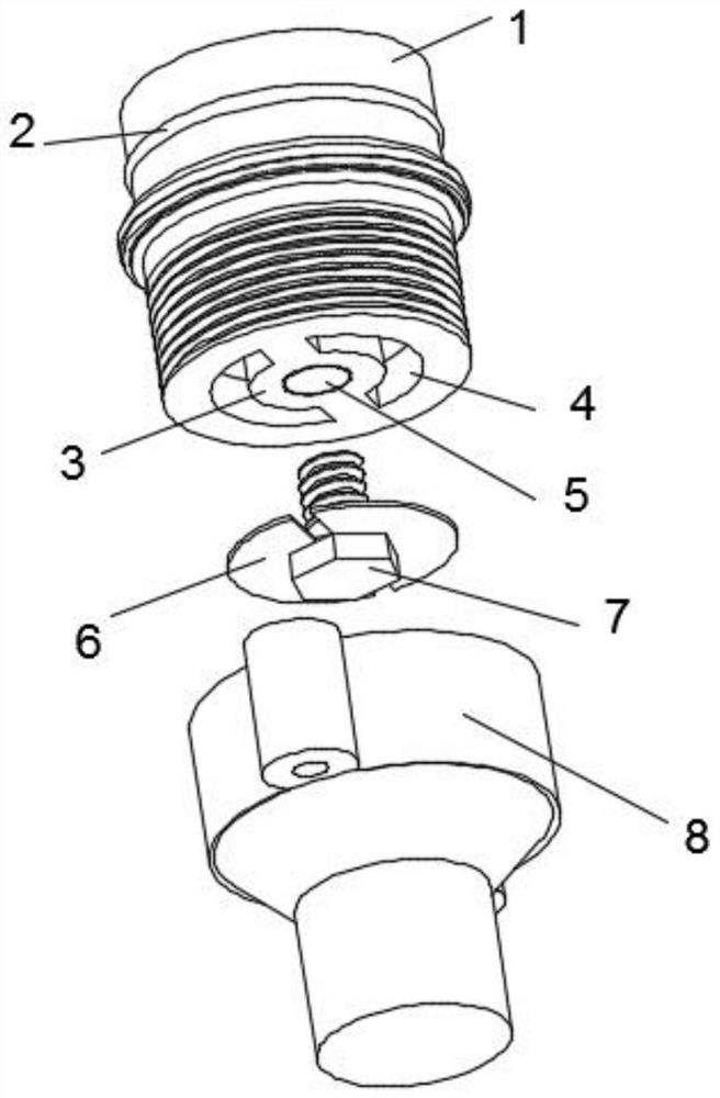
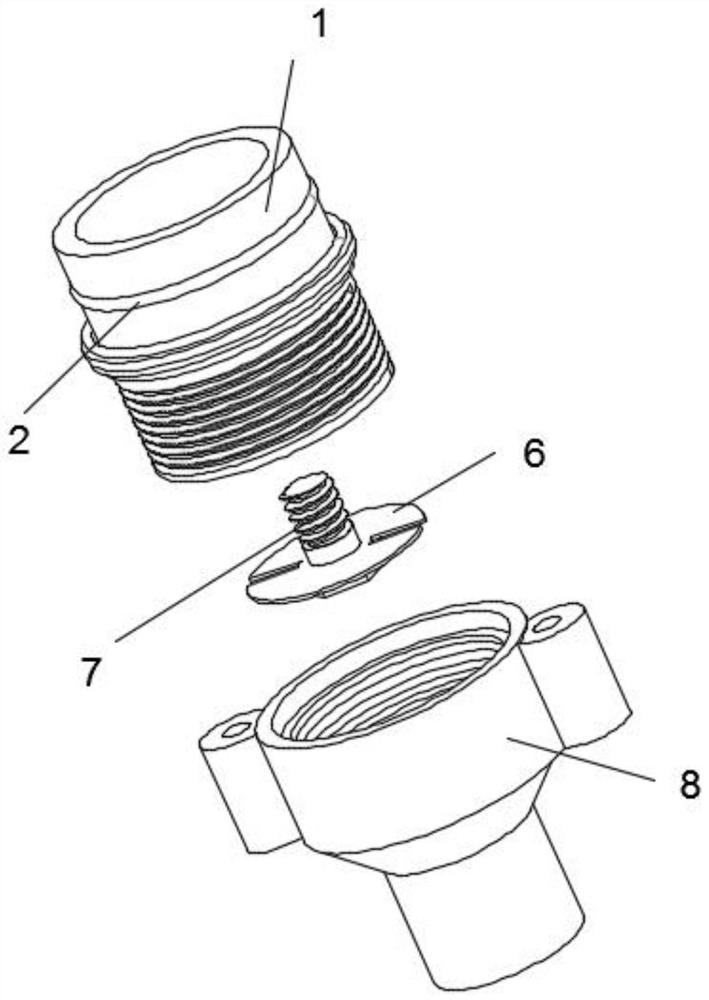
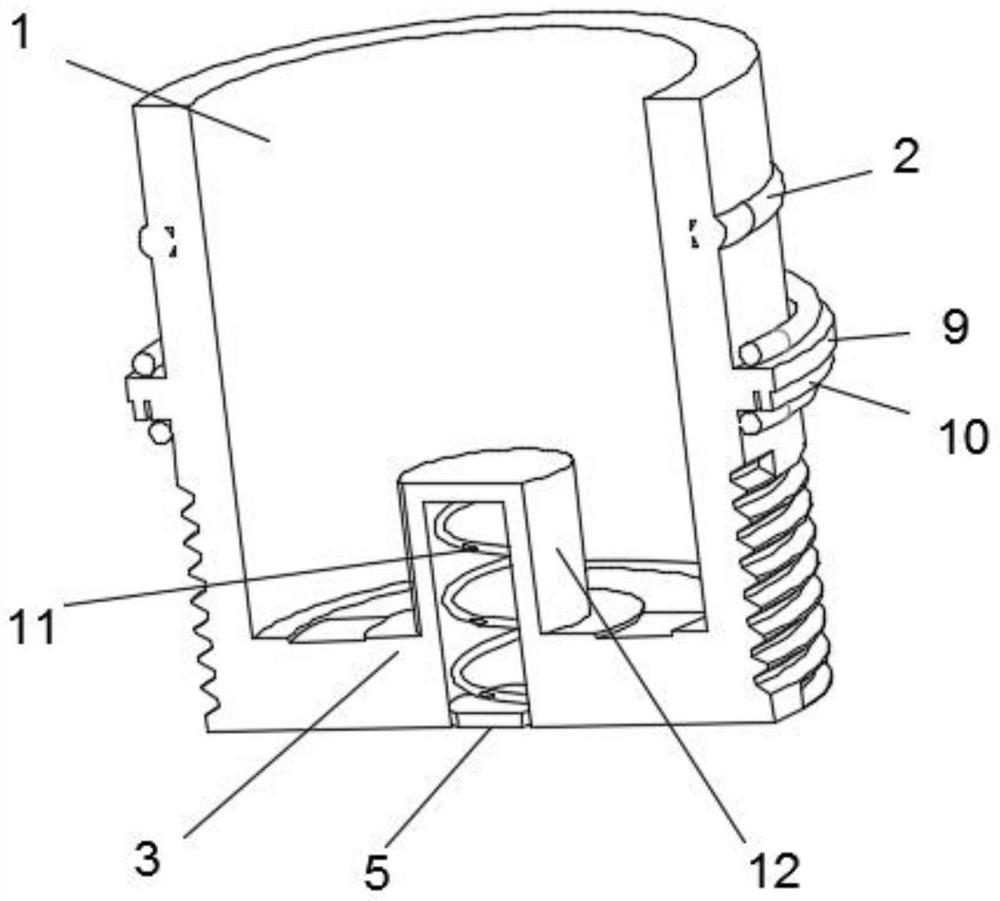
[0030] see Figure 1 to Figure 3 , the application provides a check valve, which is applied to a new type of fuel cell stack, including: a valve cover 1, a limit ring 9 is installed on the outside of the valve cover 1, and a plurality of sets of sealing rings 2 are sleeved on the outside of the valve cover 1, Gasket 10 is installed on the bottom of limit ring 9, and seal ring 2 is installed on the top and bottom of limit ring 9, and limit ring 9 tops on the top of valve body 8, and multiple groups of seal rings 2 play sealing effect, limit The gasket 10 at the bottom of the bit ring 9 acts as a seal;

[0031] The non-return part, the non-return part includes a fixed ring 3, the fixed ring 3 is installed on the bottom of the bonnet 1, the bottom of the bonnet 1 is provided with an arc-shaped channel 4, and the top of the fixed ring 3 is equipped with a fixed column 12, and the arc-shaped channel The groove 4 is opened at the bottom of the valve cover 1, which is in the shape o...

Embodiment 2

[0038] On the basis of Embodiment 1, in order to fix the connecting rod 7, the bottom of the fixed ring 3 is equipped with a baffle plate 5, and the top of the fixed ring 3 is equipped with a fixed column 12, and the inside of the fixed column 12 is provided with threads, and the fixed column 12 is equipped with a spring 11 inside, one end of the spring 11 is connected to the inner wall of the fixed column 12, the other end of the spring 11 is connected to the baffle plate 5, after the connecting rod 7 is set into the fixed column 12, under the push of the spring 11, Just make baffle plate 5 push away connecting rod 7, prevent connecting rod 7 from loosening.

Embodiment 3

[0040] On the basis of Example 2, in order to prevent the material from flowing back in the through groove 4, the bottom of the fixed ring 3 is provided with a connecting rod 7, and the outside of the connecting rod 7 is provided with a non-return plate 6. The non-return plate 6 is elastic. It can be bent and does not fit with the fixed ring 3. When the material normally flows out from the arc-shaped slot 4 from top to bottom, the check plate 6 will be bent. When the material flows back, the check plate 6 will stick to it. Secure the surface of ring 3 to prevent backflow.

[0041] Set the connecting rod 7 into the fixed column 12, the connecting rod 7 pushes the baffle plate 5 into the fixed column 12, the spring 11 is compressed, the connecting rod 7 fixes the non-return plate 6 on the bottom of the fixed ring 3, and the non-return plate 6 Cover the arc-shaped through groove 4, set the bottom of the valve cover 1 in the valve body 8, the limit ring 9 is on the top of the valv...


PUM


Abstract

The invention relates to the technical field of check valves, in particular to a check valve and a novel fuel cell stack using the check valve.The novel check valve for the fuel cell stack comprises a valve deck, and a limiting ring is installed on the outer portion of the valve deck; the fixing ring is installed at the bottom of the valve cover, an arc-shaped through groove is formed in the bottom of the valve cover, and a fixing column is installed at the top of the fixing ring; the valve body is arranged at the bottom of the valve cover; the fixing device has the beneficial effects that the fixing column is installed at the top of the fixing ring, the threads are arranged in the fixing column, the spring is installed in the fixing column, and the baffle is installed at the bottom of the spring, so that when the connecting rod is arranged in the fixing column in a sleeved mode, the spring can push the connecting rod, and the connecting rod is prevented from loosening; the check plate is arranged outside the connecting rod in a sleeving mode, the check plate has elasticity and is small in flow resistance, and during check, the check plate can abut against the bottom of the valve deck to achieve the check effect.

Description

[0001] The present application relates to the technical field of check valves, in particular to a check valve and a novel fuel cell stack using the check valve. Background technique [0002] A fuel cell is a chemical device that directly converts the chemical energy of fuel into electrical energy, also known as an electrochemical generator. The fuel cell stack is to combine the above-mentioned multiple fuel cells together to achieve the purpose of obtaining a practical voltage. Existing fuel cell stacks generally use liquid hydrogen or LNG as fuel, and the storage temperature of such liquids is extremely low, which requires that the components in the fuel cell stack system be able to adapt to the ultra-low temperature environment. [0003] Among them, the function of the check valve in the fuel cell stack is to control the flow direction of the low-temperature fluid. For example, the Chinese application patent with the notification number CN206738648U discloses a low-temperat...

Claims


Application Information

Patent Timeline
IPC IPC(8): F16K15/14F16K27/02
CPCF16K15/14F16K27/0209
Inventor 马君陆嘉君江章亮王琪张金铮曾富强
Owner 张家港富瑞阀门有限公司
Learn More