
Wind tunnel test device for aerodynamic dynamic derivative decoupling measurement

It is an aerodynamic and wind tunnel test technology, which is applied in aerodynamic test, measuring device, machine/structural component test, etc. It can solve the problem of huge workload, dynamic derivative decoupling that cannot be strongly coupled, complex implementation methods, etc. problem, to achieve the effect of improving data processing efficiency, avoiding decoupling difficulties, simplifying workload and technical difficulty

Pending Publication Date: 2022-03-01
上海华模科技有限公司
View PDF0 Cites 2 Cited by
  • Summary
  • Abstract
  • Description
  • Claims
  • Application Information

AI Technical Summary

Problems solved by technology

The calculation deviation of the dynamic derivative will bring errors to the evaluation of the dynamic characteristics of the aircraft and the design of the control system, thereby reducing the accuracy of key points in the manufacturing of the aircraft and even leading to serious consequences that the flight purpose cannot be achieved
[0003] Current aerodynamic modeling mainly relies on theoretical calculations, actual flight, and traditional wind tunnel data. The implementation method is complex and the workload is huge. In addition, traditional methods cannot directly decouple strongly coupled dynamic derivatives, requiring a large amount of post-processing data. Therefore, it is necessary to design a wind tunnel test device for decoupling measurement of aerodynamic dynamic derivatives to solve the above problems

Method used


Image

  • Wind tunnel test device for aerodynamic dynamic derivative decoupling measurement
  • Wind tunnel test device for aerodynamic dynamic derivative decoupling measurement
  • Wind tunnel test device for aerodynamic dynamic derivative decoupling measurement

Examples


Embodiment Construction

[0021] The following will clearly and completely describe the technical solutions in the embodiments of the present invention with reference to the accompanying drawings in the embodiments of the present invention. Obviously, the described embodiments are only some, not all, embodiments of the present invention.

[0022] In describing the present invention, it should be understood that the terms "upper", "lower", "front", "rear", "left", "right", "top", "bottom", "inner", " The orientation or positional relationship indicated by "outside", etc. is based on the orientation or positional relationship shown in the drawings, which is only for the convenience of describing the present invention and simplifying the description, rather than indicating or implying that the referred device or element must have a specific orientation, so as to Specific orientation configurations and operations, therefore, should not be construed as limiting the invention.

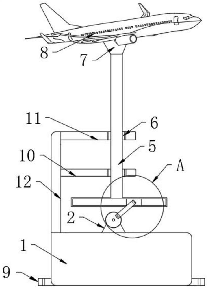
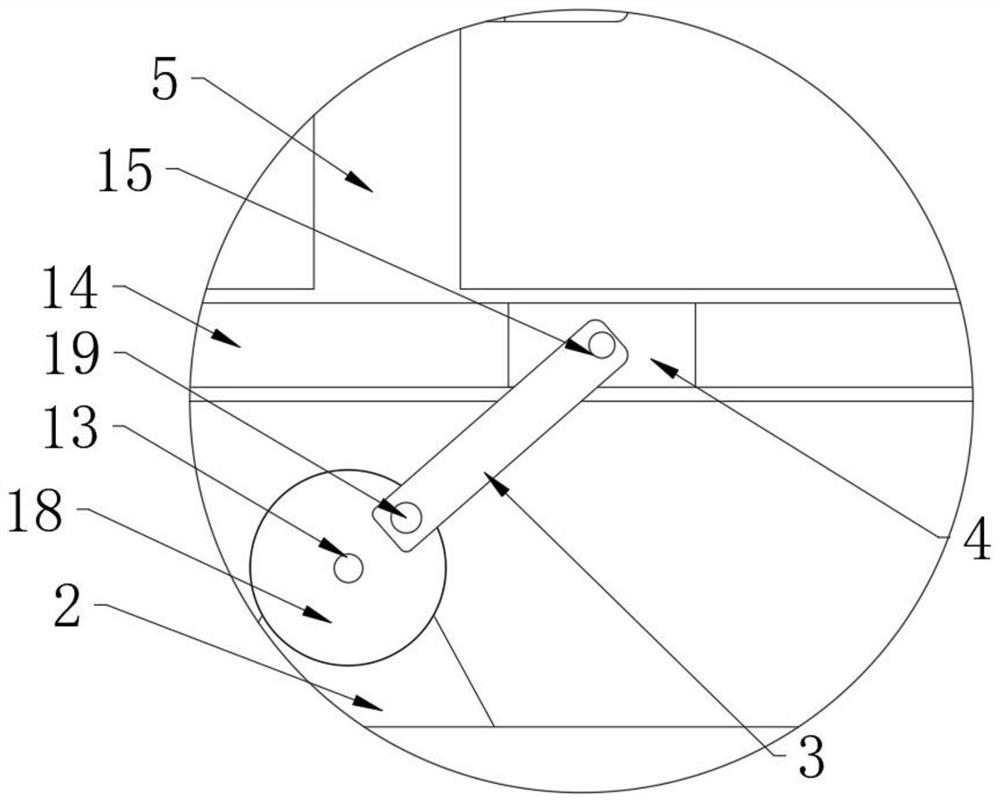
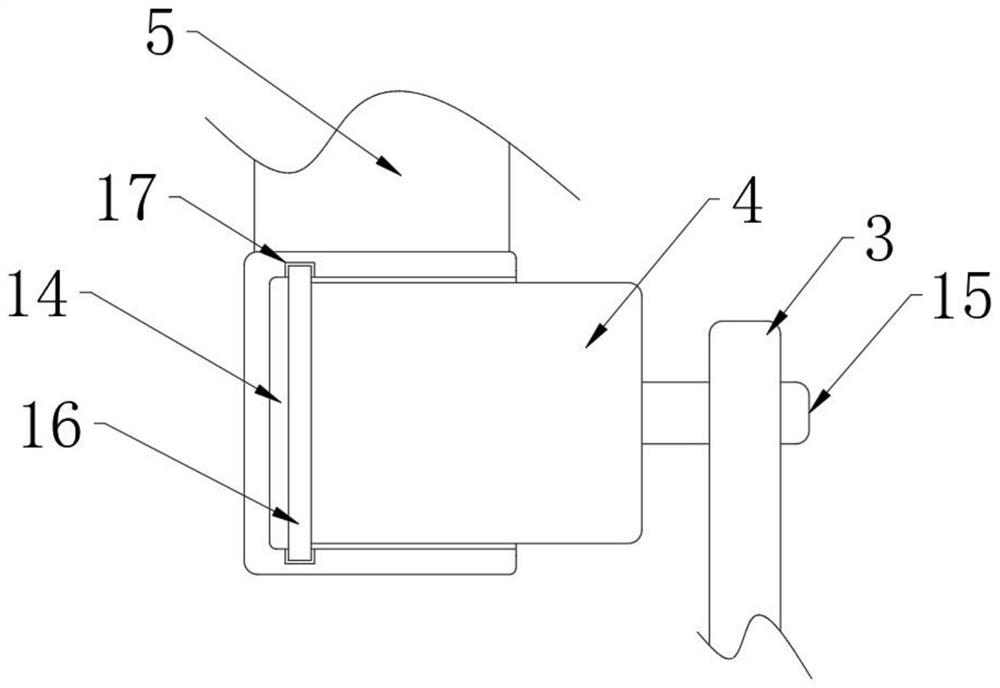
[0023] refer to Figure 1-5 ...


PUM


Abstract

A wind tunnel test device for aerodynamic dynamic derivative decoupling measurement disclosed by the present invention comprises a base station and an airplane model arranged on the base station, the upper end of the base station is fixedly connected with a mounting rack, and the base station is provided with a driving mechanism for driving the airplane model to lift. The driving mechanism comprises a servo motor fixedly connected to the upper end of the base table, an output shaft of the servo motor is fixedly connected with a rotating shaft, and the end, away from the servo motor, of the rotating shaft is fixedly connected with a rotating disc. The device is provided with the T-shaped frame and the crank, the data processing efficiency is effectively improved, the device can be used in the fields of aircraft pneumatic modeling, pneumatic model analysis, correction and verification, manufacturing of flight simulator data packets of various grades and the like, in addition, the device is simple and reliable in structure, the problem that dynamic derivatives are difficult to decouple after measurement in a coupling state can be effectively solved, and the reliability of the device is improved. And meanwhile, the workload and the technical difficulty in the pneumatic modeling process can be greatly reduced.

Description

technical field [0001] The invention relates to the technical field of aerodynamic wind tunnel test devices, in particular to a wind tunnel test device for decoupling measurement of aerodynamic dynamic derivatives. Background technique [0002] According to the different control modes and purposes, the aircraft often adopts the flight mode of rotating around its own longitudinal axis in whole or in part, and the speed is several degrees per second. In engineering practice, in order to describe the aerodynamic characteristics of the aircraft to the guidance and control system, it needs to be modeled. When modeling, the aerodynamic force is generally divided into two parts: steady and unsteady, and the unsteady part is represented by the product and expression of the dynamic derivative and the corresponding variable. The calculation deviation of the dynamic derivative will bring errors to the evaluation of the dynamic characteristics of the aircraft and the design of the cont...

Claims


Application Information

Patent Timeline
Patent Type & Authority Applications(China)
IPC IPC(8): G01M9/00G01M9/08
CPCG01M9/00G01M9/08Y02T90/00
Inventor 喻浩文李鹏王林毛忠明
Owner 上海华模科技有限公司
Learn More