Searching and scanning control method of photoelectric turret for radar identification target area

A technology of photoelectric turret and target area, applied in the direction of feedback control, radio wave measurement system, instrument, etc., can solve the problems of low degree of automation, inaccurate range, small telephoto field of view, etc., to reduce missed targets The probability of solving the problem of low degree of automation and speeding up the search speed

Pending Publication Date: 2022-03-01
LUOYANG INST OF ELECTRO OPTICAL EQUIP OF AVIC
View PDF0 Cites 1 Cited by
  • Summary
  • Abstract
  • Description
  • Claims
  • Application Information

AI Technical Summary

Problems solved by technology

[0003] However, since the radar gives the area range where the target may appear, this range is often not accurate enough
At present, the long-focus field of view of the sensor of the photoelectric turret is very small, and it is difficult to cover the entire target area. It is often impossible to find the target after aligning with the center of the target area. Therefore, the existing search method is to align the photoelectric turret with the center of the target area. If the target is not found, use the manual search method to continue to manually search for the target in the surrounding area, which is not only low in automation and time-consuming, but also because the target position is changing, it is often difficult to find the target

Method used


Image

  • Searching and scanning control method of photoelectric turret for radar identification target area
  • Searching and scanning control method of photoelectric turret for radar identification target area

Examples


Embodiment Construction

[0032] The embodiments described below by referring to the figures are exemplary and are intended to explain the present invention and should not be construed as limiting the present invention.

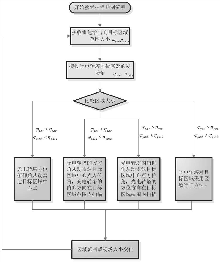
[0033] refer to figure 1 , 2 As shown, a kind of photoelectric turret of the present invention searches and scans the control method to radar identification target area as follows:

[0034] With the cooperation of the radar, the photoelectric turret can search and scan the target area identified by the radar. First of all, the angle between the photoelectric turret and the radar needs to be aligned and corrected, and the angle given by the radar corresponds to the optical axis angle of the photoelectric turret. Then the photoelectric turret receives the range information of the target area given by the radar after the radar finds the target.

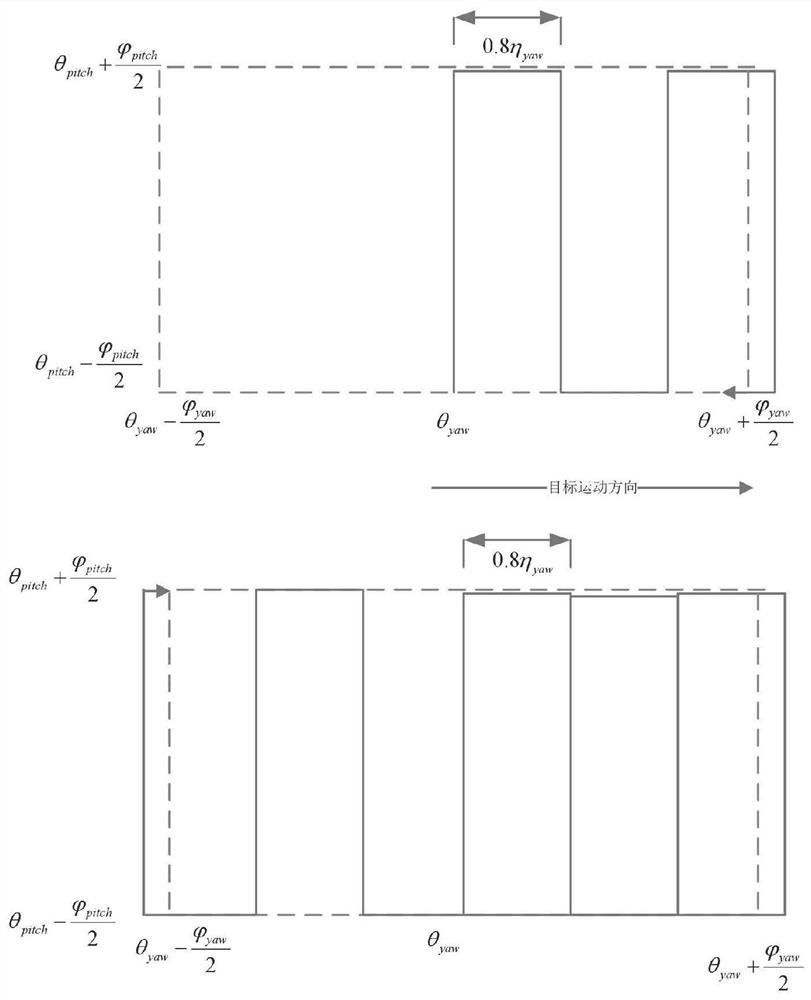
[0035] The azimuth angle of the photoelectric turret corresponding to the central point of the area where the target may appear is θ yaw , ...


PUM


Abstract

The invention discloses a searching and scanning control method of a photoelectric turret for a radar identification target area, and belongs to an automatic control technology. The scanning search mode and the search range are automatically calculated according to the view field size of the turret sensor and the target possible range given by the radar, and full-automatic search scanning is achieved. In the area searching and scanning process, the photoelectric turret can switch searching and scanning modes according to the target area range given by the radar and the field angle information range of the current sensor, an appropriate scanning mode is selected from the four scanning modes according to the size of the target area range and the field angle range, and scanning parameters are calculated. Therefore, the whole target area range can be scanned under the condition that the target area changes continuously. Practical tests prove that the searching and scanning control method realizes full-automatic searching and scanning, human intervention is not needed, the target can be found when the range given by the radar is not accurate enough, the efficiency is greatly improved, and the probability of missing the target is reduced.

Description

technical field [0001] The invention belongs to the field of automatic control, and in particular relates to a search and scan control method of a photoelectric turret for a radar identification target area. Background technique [0002] At present, the use of photoelectric turrets and radars to work together is an effective way to achieve day and night search, tracking, surveillance, and identification of air area targets. The photoelectric turret can be aimed at the target area detected by the radar, and detect the contour characteristics and shape information of the target that is difficult to detect by the radar. [0003] However, since the radar gives the range of areas where the target may appear, this range is often not accurate enough. At present, the long-focus field of view of the sensor of the photoelectric turret is very small, and it is difficult to cover the entire target area. It is often impossible to find the target after aligning with the center of the tar...

Claims


Application Information

Patent Timeline
Patent Type & Authority Applications(China)
IPC IPC(8): G01S7/481G05D3/12
CPCG01S7/4817G05D3/12
Inventor 张龙浩杜明昊昝宝亮刘念沈腾申宇元
Owner LUOYANG INST OF ELECTRO OPTICAL EQUIP OF AVIC
Why Eureka
Try Eureka