Lead design method and lead structure of 110kV double-winding vehicle-mounted transformer

A design method, 1.110kv technology, applied in the direction of transformer/inductor coil/winding/connection, transformer/inductor cooling, inductor/transformer/magnet manufacturing, etc., can solve the problem of small operable space and reduce welding difficulty , Unified position and size, strong stability

Pending Publication Date: 2022-03-01
SHANDONG POWER EQUIP
View PDF0 Cites 0 Cited by
  • Summary
  • Abstract
  • Description
  • Claims
  • Application Information

AI Technical Summary

Problems solved by technology

However, limited by the installation location and space of the vehicle-mounted transformer, the position and form of the high-voltage bushing of the vehicle-mounted transformer are relatively special, and the internal operable space is relatively small
The conventional lead wire structure of transformer products is no longer applicable, so it is necessary to study a new lead wire structure design method and lead wire structure form suitable for vehicle-mounted transformers

Method used


Image

  • Lead design method and lead structure of 110kV double-winding vehicle-mounted transformer
  • Lead design method and lead structure of 110kV double-winding vehicle-mounted transformer
  • Lead design method and lead structure of 110kV double-winding vehicle-mounted transformer

Examples


Embodiment Construction

[0023] The technical solutions of the present invention will be clearly and completely described below in conjunction with the accompanying drawings. Apparently, the described embodiments are part of the embodiments of the present invention, not all of them.

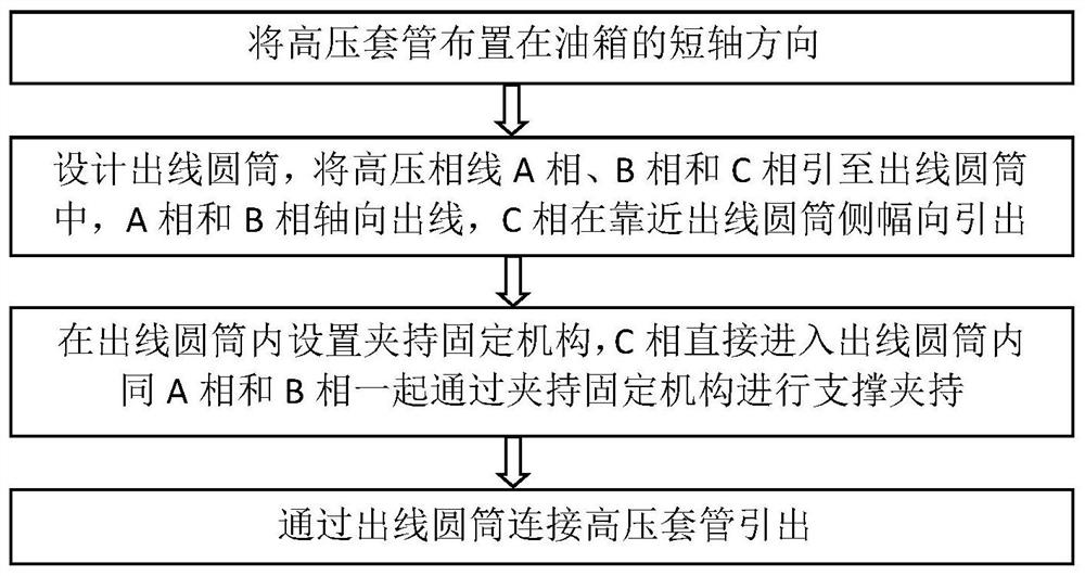
[0024] Such as figure 1 As shown in FIG. 1 , it is a flow chart of the lead design method according to the embodiment of the present invention. A lead design method for a 110kV double-winding vehicle-mounted transformer, comprising the following steps:

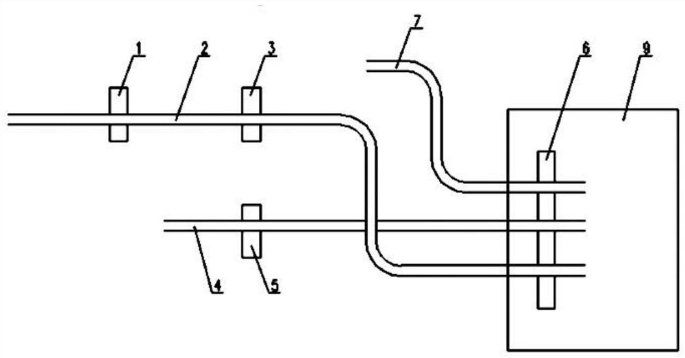
[0025] Step 1. Arrange the high-voltage bushing in the direction of the short axis of the fuel tank.

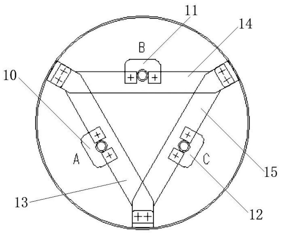
[0026] Step 2. Design the outlet cylinder, lead the high-voltage phase line A phase, the high-voltage phase line B phase and the high-voltage phase line C phase into the outlet cylinder. The wire clamp support clamps the high-voltage phase line A phase and the high-voltage phase line B phase and leads them to the outlet cylinder, and the high-voltage phase line C phas...


PUM


Abstract

The invention relates to a 110kV duplex-winding vehicle-mounted transformer lead design method, which comprises the following steps of: arranging a high-voltage bushing in the short axis direction of an oil tank, leading a high-voltage phase line A phase, a high-voltage phase line B phase and a high-voltage phase line C phase into a wire outlet cylinder, arranging a clamping and fixing mechanism in the wire outlet cylinder, and leading out the high-voltage bushing through connecting the wire outlet cylinder. The invention further relates to a lead structure of the 110kV duplex-winding vehicle-mounted transformer, the high-voltage bushing is arranged in the short axis direction of an oil tank, the high-voltage bushing is connected and led out through a wire outlet cylinder, a high-voltage phase line A phase and a high-voltage phase line B phase are axially led out, and the high-voltage phase line A phase and the high-voltage phase line B phase are supported and clamped through relatively independent wire clamps and led to the high-voltage bushing side of the oil tank. The C phase of the high-voltage phase line is radially led out at the side close to the wire outlet cylinder, and a clamping and fixing mechanism is arranged in the wire outlet cylinder. The conventional arrangement mode of the high-voltage bushings needs a large fuel tank width size, the width of the fuel tank is reduced, high-voltage phase lines do not interfere with one another, wiring is more visual, the creepage possibility is reduced, and the high-voltage bushings have good mechanical strength and reliable electrical strength.

Description

technical field [0001] The invention belongs to the technical field of transformer production and manufacturing, and in particular relates to a lead wire design method and a lead wire structure of a 110kV double-winding vehicle-mounted transformer. Background technique [0002] Compared with conventional transformer products, vehicle-mounted transformers are small in size and easy to move, and have outstanding advantages in power maintenance and emergency repairs. However, limited by the installation location and installation space of the vehicle-mounted transformer, the position and form of the high-voltage bushing of the vehicle-mounted transformer are relatively special, and the internal operable space is relatively small. Conventional transformer product lead structure is no longer applicable, which requires research on a new lead structure design method and lead structure form suitable for vehicle-mounted transformers. Contents of the invention [0003] In view of th...

Claims


Application Information

Patent Timeline
Patent Type & Authority Applications(China)
IPC IPC(8): H01F27/29H01F27/28H01F27/14H01F41/00
CPCH01F27/29H01F27/28H01F27/14H01F41/00
Inventor 刘莎初萌王兴烛
Owner SHANDONG POWER EQUIP
Why Eureka
Try Eureka