Adaptive beam width multi-beam forming method for obliquely placed array plane

An obliquely placed, multi-beam technology, applied in the field of active phased array systems, can solve problems affecting direction finding accuracy, beam pattern distortion, system beam resource waste, etc., to improve direction finding accuracy and reduce pattern Distortion, the effect of optimizing signal sensitivity

Pending Publication Date: 2022-03-01
中国船舶重工集团公司第七二三研究所
View PDF0 Cites 0 Cited by
  • Summary
  • Abstract
  • Description
  • Claims
  • Application Information

AI Technical Summary

Problems solved by technology

The traditional adjustment method is often only realized by changing the original two-dimensional width of each beam. For side beams at extreme positions such as high elevation and high azimuth, excessive broadening will cause distortion of the beam pattern, which will seriously affect the direction fi

Method used


Image

  • Adaptive beam width multi-beam forming method for obliquely placed array plane
  • Adaptive beam width multi-beam forming method for obliquely placed array plane
  • Adaptive beam width multi-beam forming method for obliquely placed array plane

Examples


Embodiment

[0045] In order to verify the effectiveness of the scheme of the present invention, the following experiments were carried out.

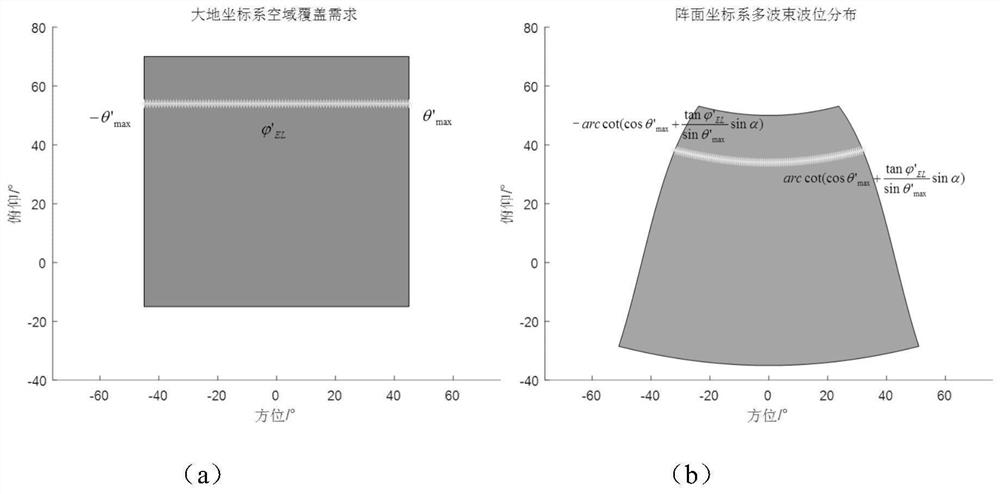
[0046] In this embodiment, the operating frequency of the phased array is 6GHz, the aperture of the array is 1m×1m, and the coverage of the system airspace is -10°~55° in pitch and -30°~30° in azimuth in the geodetic coordinate system. The angle is 10°, and the number of multi-beams in each layer is 30. When the front surface receives the signal, when the elevation scan is directed to 50°, the beam forming method of the present invention is applied, and the process is as follows.

[0047] 1) According to formula (1), the longitudinal wave width (3dB attenuation) of the beam at the pitching position is calculated to be 3.31°, and this value is taken as the actual longitudinal wave width value of the amplitude ratio direction finding of the two beams in pitch, which can compensate the pitch direction finding error. .

[0048] 2) Calculate the upper ...


PUM


Abstract

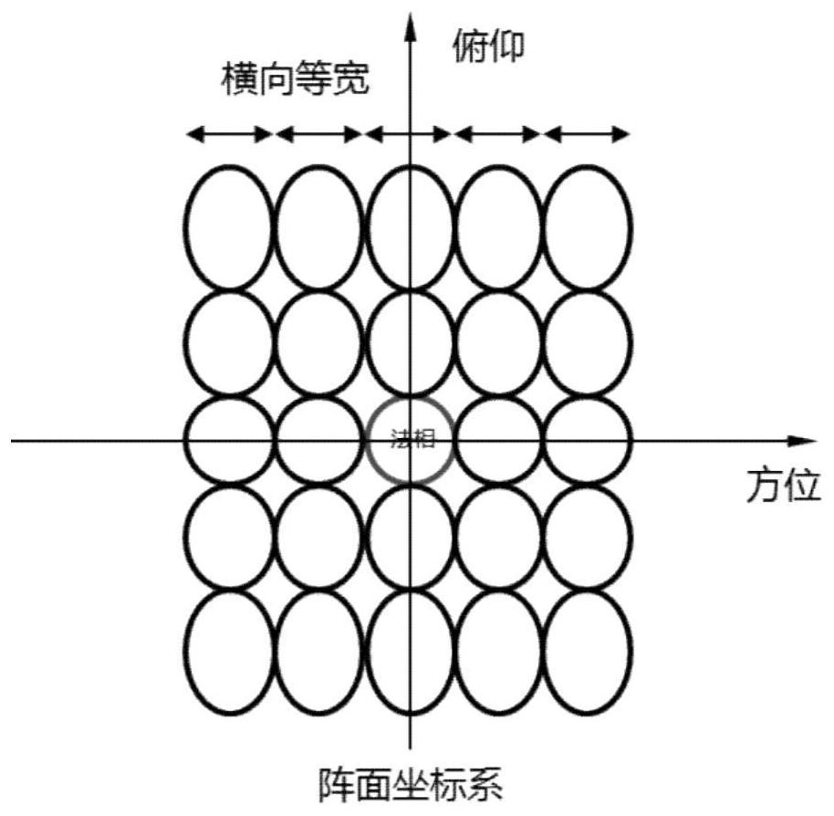
The invention provides a self-adaptive beam width multi-beam forming method for an inclined array plane, which comprises the following steps of: performing traversal search on an airspace coverage range by adopting an azimuth multi-beam pitching scanning mode, and performing matching compensation on a pitching directional angle according to a vertical wave width of a pitching direction where transverse multi-beams are positioned; and keeping the horizontal wave width of each wave beam in the horizontal direction of the same pitching layer to be the same as the horizontal wave width of the wave beam in the azimuth method of the layer through a Taylor window coefficient broadening method. According to the method, space resources for receiving multiple beams at different pitch angles of the phased array plane are fully utilized, beam broadening is performed only in the horizontal dimension, directional diagram distortion of side beams is reduced as much as possible on the premise that the airspace coverage requirement of a geodetic coordinate system is met, and the direction finding precision of the array plane is improved.

Description

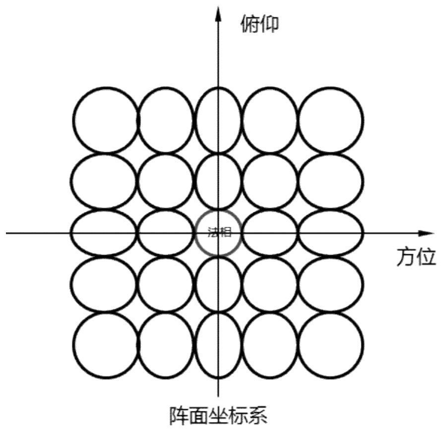
technical field [0001] The invention relates to an active phased front system, in particular to an adaptive beam width multi-beam forming method of an obliquely placed front. Background technique [0002] According to the actual application scenarios of the antenna array, and in order to reduce the influence of the multipath effect, the phased array system often adopts the fastening method of inclined installation. Under the phased front system that receives signals in the azimuth multi-beam elevation scanning method, the airspace coverage remains unchanged, and the change of the installation inclination will require readjustment and optimization of the multi-beam arrangement of the front. The traditional adjustment method is often only realized by changing the original two-dimensional width of each beam. For side beams at extreme positions such as high pitch and high azimuth, excessive widening will cause distortion of the beam pattern, which will seriously affect the direc...

Claims


Application Information

Patent Timeline
IPC IPC(8): H01Q3/26H01Q23/00H01Q21/00H01Q1/00H01Q25/00G06F17/15
CPCH01Q3/2605H01Q23/00H01Q1/002H01Q21/00H01Q25/002G06F17/15
Inventor 于勇王坚黄华吴海韩光威刘咏钟文王喜鹏顾力伟杨坡吴照宪赵艳秋张文君
Owner 中国船舶重工集团公司第七二三研究所
Why Eureka
Try Eureka