Varactor circuit with low phase noise

A low phase noise and phase noise technology, applied in the direction of reliability improvement and modification, can solve the problems of inability to reduce noise and VCO performance impact, and achieve the effect of improving Q value and applicability

Pending Publication Date: 2022-03-01
南京极景微半导体有限公司
View PDF0 Cites 0 Cited by
  • Summary
  • Abstract
  • Description
  • Claims
  • Application Information

AI Technical Summary

Problems solved by technology

[0005] Aiming at the deficiencies of the prior art, the present invention provides a varactor circuit with low phase noise, which solves the problem that the larger resistance value of the current varactor circuit will contribute noise, but the smaller resistance value will affect the performance of the VCO. The problem that the noise cannot be reduced while increasing the resistance value

Method used


Image

  • Varactor circuit with low phase noise
  • Varactor circuit with low phase noise
  • Varactor circuit with low phase noise

Examples


Embodiment 1

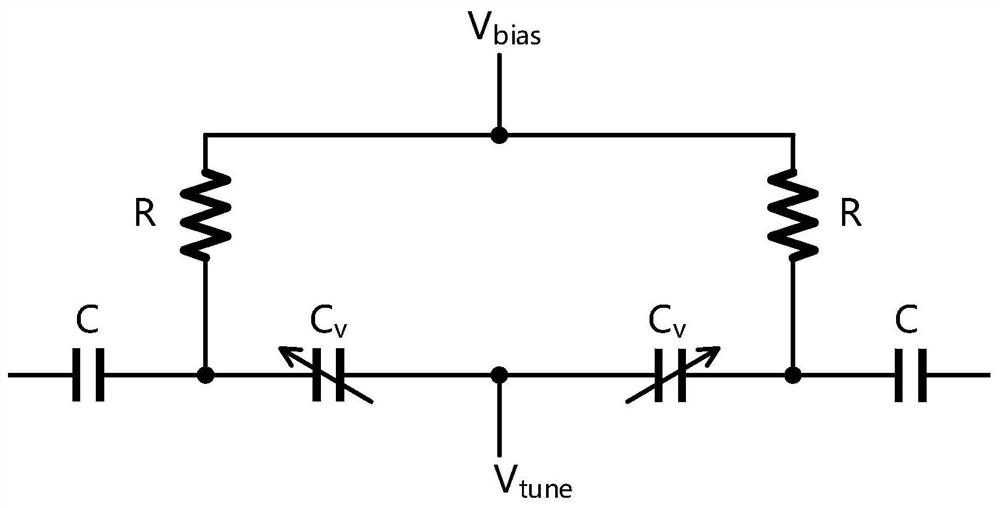
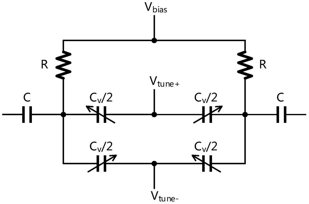
[0022] refer to Figure 1-Figure 3 , a varactor circuit with low phase noise, including two capacitors and two resistors, the two capacitors and the two resistors are connected in series, and the two resistors are located between the two capacitors, and there are multiple capacitors connected in parallel between the two resistors The first variable capacitor, and the two common terminal nodes are located between the capacitor and the resistor, a plurality of second variable capacitors are connected in parallel on the two common terminal nodes, and the first variable capacitor and the second variable capacitor have the same gain but The polarity is opposite, because the thermal noise of the resistor is common-mode noise, if the first variable capacitor and the second variable capacitor with the same gain but opposite polarity are selected and connected to the resistor in the same way, the thermal noise of the resistor is within a certain The phase noise generated by the first v...

Embodiment 2

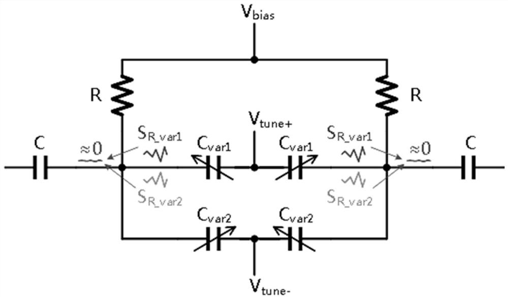
[0026] refer to Figure 1-Figure 3 , a varactor circuit with low phase noise, including two capacitors and two resistors, the two capacitors and the two resistors are connected in series, and the two resistors are located between the two capacitors, and there are multiple capacitors connected in parallel between the two resistors The first variable capacitor, and the two common terminal nodes are located between the capacitor and the resistor, a plurality of second variable capacitors are connected in parallel on the two common terminal nodes, and the first variable capacitor and the second variable capacitor have the same gain but The polarity is opposite, because the thermal noise of the resistor is common-mode noise, if the first variable capacitor and the second variable capacitor with the same gain but opposite polarity are selected and connected to the resistor in the same way, the thermal noise of the resistor is within a certain The phase noise generated by the first v...


PUM


Abstract

The invention relates to the technical field of varactor circuits, and discloses a low-phase noise varactor circuit, which comprises two capacitors and two resistors, the two capacitors and the two resistors are connected in series, the two resistors are positioned between the two capacitors, a plurality of first variable capacitors are connected in parallel between the two resistors, and a plurality of second variable capacitors are connected in parallel between the two resistors. The two common end nodes are located between the capacitor and the resistor, a plurality of second variable capacitors are connected to the two common end nodes in parallel, and the first variable capacitor and the second variable capacitors are the same in gain but opposite in polarity. According to the invention, the first variable capacitor and the second variable capacitor with the same gain and opposite polarity are selected and connected to the resistor in the same way, so that the phase noise generated by the thermal noise of the resistor through the first variable capacitor at a certain moment can be exactly counteracted by the phase noise generated by the second variable capacitor; and the resistance can select a larger value to improve the quality factor Q value.

Description

technical field [0001] The invention relates to the technical field of varactor circuits, in particular to a varactor circuit with low phase noise. Background technique [0002] With the rapid development of integrated circuits, the system has higher and higher requirements for the clock circuit, and the voltage-controlled oscillator (VCO), as a very important module in the clock circuit, has been paid more and more attention. In scenarios where high-speed and low-noise requirements are required, LC-VCO has an irreplaceable position. Among them, variable capacitors have a significant impact on the noise and other performance of VCOs. The C-V curve of variable capacitors is greatly affected by the process. In order to be more flexible in use, And from the perspective of reliability, reducing the nonlinearity of the variable capacitor, reducing Kvdd, etc., the C-V curve is usually shifted by changing the voltage value of the bias voltage Vbias, so that the Kv of the VCO (the r...

Claims


Application Information

Patent Timeline
Patent Type & Authority Applications(China)
IPC IPC(8): H03K19/003
CPCH03K19/003
Inventor 杨祎黄继超苗俊涛贾萃华郑彦锋
Owner 南京极景微半导体有限公司
Why Eureka
Try Eureka