Sprayer for burn department

A sprayer and installation tube technology, which is applied in the direction of nebulizers for treatment, medical devices, medical devices, etc., can solve the problems of drug spraying, the inability to adjust the temperature of the liquid medicine according to the demand, and the waste of the liquid medicine, so as to avoid slippery effect

Pending Publication Date: 2022-03-04
李山福
View PDF7 Cites 1 Cited by
  • Summary
  • Abstract
  • Description
  • Claims
  • Application Information

AI Technical Summary

Problems solved by technology

[0005] In order to overcome the shortcomings of existing nebulizers that are easy to accidentally touch the medicine, and the temperature of the medicine solution cannot be adjusted according to the demand, the purpose of the present invention is to provide a burn nebulizer that can avoid the waste of the medicine solution and can adjust the temperature of the medicine solution at the same time

Method used


Image

  • Sprayer for burn department
  • Sprayer for burn department
  • Sprayer for burn department

Examples


Embodiment 1

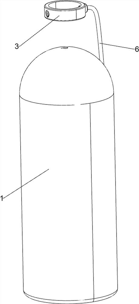
[0027] A nebulizer for burns, such as Figure 1-9 As shown, it includes a bottle body 1, an installation cylinder 2, a ring 3, an atomizing nozzle 4, a housing 5, a hose 6, an extrusion mechanism 7 and a heating mechanism 8, and the top of the bottle body 1 is provided with an installation cylinder 2. The upper part of the tube 2 is provided with a circular ring 3, the left side of the circular ring 3 is provided with an atomizing nozzle 4, the right side of the circular ring 3 and the bottle body 1 is provided with a housing 5, and the right side of the circular ring 3 is provided with a hose 6. The tube 6 has a one-way valve, the installation cylinder 2 is provided with an extruding mechanism 7 , and the installation cylinder 2 is provided with a heating mechanism 8 .

[0028] When using this device, the staff sucks the liquid in the bottle body 1 into the hose 6 through the extrusion mechanism 7, and the liquid in the hose 6 enters the ring 3 and is sprayed out through the ...

Embodiment 2

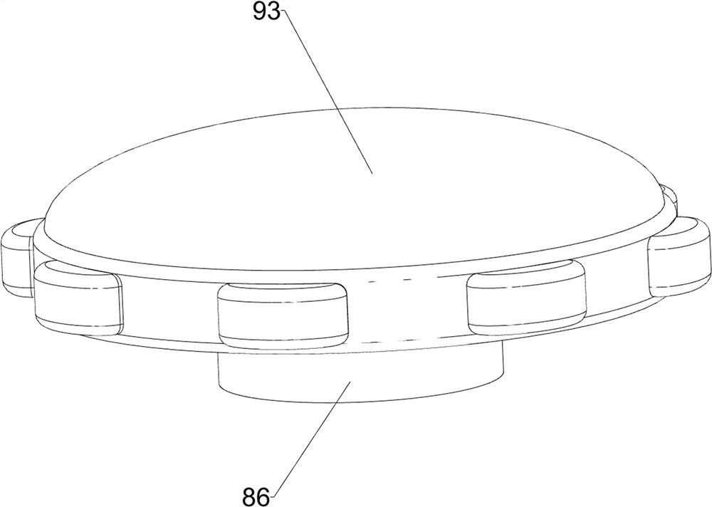
[0034] On the basis of Example 1, such as figure 1 , Figure 7 and Figure 8 As shown, it also includes a rotating mechanism 9, the rotating mechanism 9 includes a push block 91, a second block 92 and a handle 93, the top of the installation block 86 is symmetrically provided with a push block 91, and the top of the installation cylinder 2 is symmetrically provided with a second block. Both the stopper 92 and the second stopper 92 cooperate with the pusher 91 , and a handle 93 is provided on the top of the installation block 86 .

[0035] When using the device, the staff turns the handle 93, the handle 93 rotates to drive the installation block 86 to rotate, and the rotation of the installation block 86 drives the push block 91 to rotate. When the push block 91 rotates to contact with the second block 92, the second block 92 limits the pushing block 91, so that it is more convenient for the staff to rotate the mounting block 86.

[0036] On the basis of Example 1, such as F...


PUM


Abstract

The invention relates to a sprayer, in particular to a sprayer for the burn department. According to the sprayer for the burn department, waste of liquid medicine can be avoided, and meanwhile the temperature of the liquid medicine can be adjusted. A sprayer for the burn department comprises a bottle body. The mounting cylinder is mounted on the bottle body; the circular ring is mounted on the mounting cylinder; the atomizing nozzle is mounted on the circular ring; the shell is mounted between the circular ring and the bottle body; the hose is mounted on the circular ring and is provided with a one-way valve; the extrusion mechanism is mounted in the mounting cylinder; and the heating mechanism is mounted in the mounting cylinder. Liquid in a bottle body can be extruded to a circular ring through an extrusion mechanism and sprayed out through an atomization spray head, the liquid can be heated according to needs through a heating mechanism, a worker can rotate a mounting block more conveniently through a rotating mechanism, and the worker can place solid sodium hydroxide into a placement pipe more conveniently through a pushing mechanism; the anti-skidding sleeve is matched with the handrail, so that people can hold the bottle body conveniently, and skidding is avoided.

Description

technical field [0001] The invention relates to a nebulizer, in particular to a nebulizer for burns department. Background technique [0002] Nebulizer is a device commonly used to spray drugs in the medical field. It is mostly used in stomatology, respiratory and burn departments. Generally, the drug is directly applied to the lesion. It has the advantages of small dose, quick effect, small side effects and convenient use. . [0003] At present, the existing nebulizers for burns generally directly press the nozzle to make the liquid medicine spray out, which may cause the medicine to be sprayed out due to accidental touch, resulting in unnecessary waste of liquid medicine, and the temperature of the liquid medicine cannot be adjusted according to the demand. [0004] Therefore, it is necessary to design a nebulizer for burns that can avoid the waste of medicinal solution and can regulate the temperature of the medicinal solution to solve the above problems. Contents of t...

Claims


Application Information

Patent Timeline
Patent Type & Authority Applications(China)
IPC IPC(8): A61M35/00A61M11/00
CPCA61M35/003A61M11/00A61M2205/3368
Inventor 李山福
Owner 李山福
Why Eureka
Try Eureka