Defibrillator
A defibrillator and inner cavity technology, applied in the field of defibrillators, can solve the problem that the defibrillator is difficult to take into account the miniaturization and heat dissipation effect, and achieve the effect of avoiding temperature rise, solving heat dissipation problems, and meeting working temperature requirements.
- Summary
- Abstract
- Description
- Claims
- Application Information
AI Technical Summary
Problems solved by technology
Method used
Image

Examples
Embodiment 1
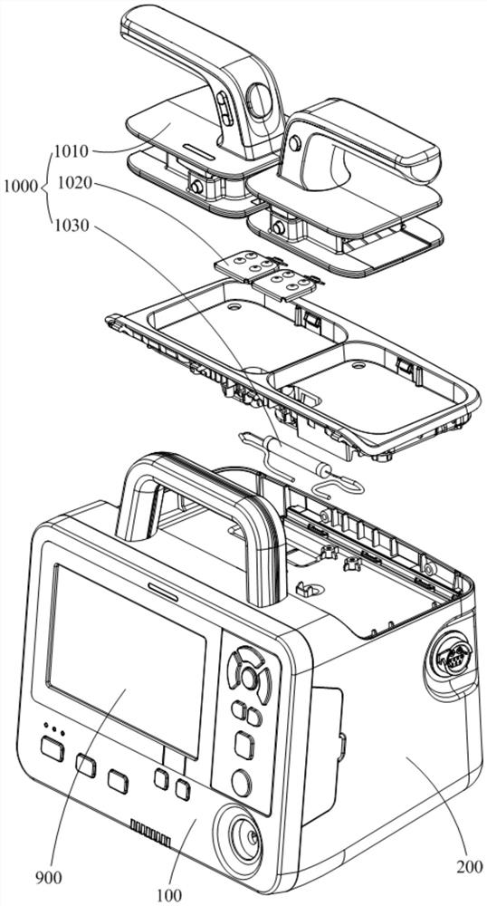
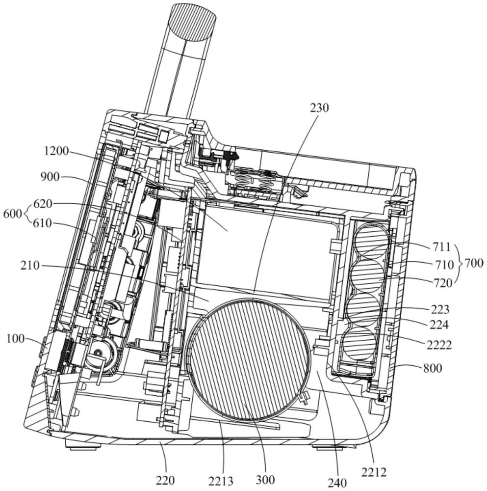
[0024] Such as Figure 1-8 As shown, the defibrillator provided by Embodiment 1 of the present invention includes a front shell 100, a rear shell 200, a defibrillation capacitor 300, and a release resistor 400. The front shell 100 is connected to the rear shell 200 to form an inner cavity 1200. Both the defibrillation capacitor 300 and the release resistor 400 are arranged in the inner cavity 1200 , and the defibrillation capacitor 300 is arranged close to the bottom of the inner cavity 1200 , and the release resistor 400 is arranged near the top of the inner cavity 1200 . The release resistor 400 is mainly used to discharge energy. During work, since a large amount of energy will be directly discharged on the release resistor 400, it will cause a sharp temperature rise of the release resistor 400. Therefore, the release resistor 400 is a One of the most important heating components in the trillometer. In the embodiment of the present invention, the release resistor 400 is ar...
Embodiment 2
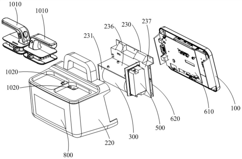
[0059] refer to figure 2 , image 3 and Figure 9 As shown, the difference between the defibrillator provided in this embodiment and the first embodiment is that this embodiment also includes an optional module 1100 on the basis of the first embodiment, and the setting of the DC-AC converter 500 in this embodiment The location is different from that of the DC / AC converter 500 in the first embodiment.
[0060]Specifically, in this embodiment, the matching module 1100 is a carbon dioxide detection module for detecting carbon dioxide, the DC-AC converter 500 is set in the second storage tank 236, and the matching module 1100 is set in the third storage tank. Inside the groove 237. The carbon dioxide detection module is a heat-sensitive component, and placing the carbon dioxide detection module in the third storage tank 237 can help reduce the influence of the carbon dioxide detection module from rising hot air in the inner cavity 1200 . Of course, the optional module 1100 is...
Embodiment 3
[0064] The difference between the defibrillator provided in this embodiment and Embodiment 1 and Embodiment 2 mainly lies in the arrangement of the DC-AC converter 500 . Specifically, in Embodiment 1 and Embodiment 2, the DC-AC converter 500 is arranged in the inner cavity 1200; while in this embodiment, the DC-AC converter 500 is arranged outside the inner cavity 1200, that is, the battery 700 is not installed in the rear shell 200 , the front shell 100 or the rear shell 200 is provided with a first socket (not shown) for plugging the connector of the DC-AC converter 500 , and the first socket is electrically connected to the circuit board assembly 600 . In some embodiments, the connector includes a connecting wire. In a specific application, the DC-AC converter 500 is plugged into the first plug interface through the connector, so as to realize the electrical connection between the DC-AC converter 500 and the circuit board assembly 600 . In this embodiment, the DC-AC conver...
PUM
 Abstract
Description
Claims
Application Information
 - R&D
- Intellectual Property
- Life Sciences
- Materials
- Tech Scout
- Unparalleled Data Quality
- Higher Quality Content
- 60% Fewer Hallucinations
Browse by: Latest US Patents, China's latest patents, Technical Efficacy Thesaurus, Application Domain, Technology Topic, Popular Technical Reports.
© 2025 PatSnap. All rights reserved.Legal|Privacy policy|Modern Slavery Act Transparency Statement|Sitemap|About US| Contact US: help@patsnap.com