Movable pneumatic manipulator

A pneumatic manipulator and mobile technology, applied in the direction of manipulators, chucks, manufacturing tools, etc., can solve the problems of affecting the accuracy of grasping objects and affecting work efficiency, and achieve the effect of facilitating movement and position adjustment, reducing cost and execution difficulty

Pending Publication Date: 2022-03-04
TIANJIN POLYTECHNIC UNIV
View PDF9 Cites 0 Cited by
  • Summary
  • Abstract
  • Description
  • Claims
  • Application Information

AI Technical Summary

Problems solved by technology

[0003] At present, manipulators are used in many occasions, such as university laboratories, manufacturing, etc., and have made more or less progress. However, when grasping different

Method used


Image

  • Movable pneumatic manipulator
  • Movable pneumatic manipulator
  • Movable pneumatic manipulator

Examples


Embodiment 1

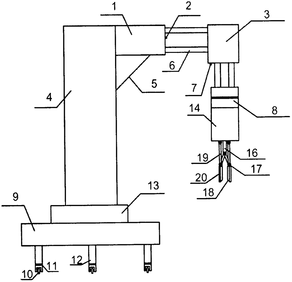
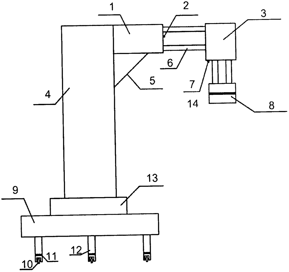
[0021] Such as figure 1 A movable pneumatic manipulator is shown, which includes a mechanical claw linkage part and a mechanical claw placed on the linkage part. The mechanical claw linkage part is provided with a wheel bracket 12, a wheel 10, a load-carrying chassis 9, a rotating bearing 11, and a rotating cylinder 13, fixed frame 4, telescopic cylinder ① 1, support frame 5, limit switch ① 2, telescopic arm 6, telescopic cylinder ② 3, limit switch ② 7, mechanical claw fixed frame 8, wherein, the wheel bracket 12 is respectively connected with the wheel 10, The rotating bearing 11 is connected to the bearing chassis 9, and the bearing chassis 9 is connected to the rotating cylinder 13, and the rotating cylinder 13 is connected to the cylinder fixing frame 4, and the cylinder fixing frame 4 is connected to the telescopic cylinder ① 1 and the support frame 5 respectively. The telescopic cylinder ①1 is connected with the telescopic arm 6 and the limit switch ①2 respectively, the ...

Embodiment 2

[0024] Such as figure 1 As shown, a movable pneumatic manipulator, its use steps are as follows,

[0025] (1) A movable pneumatic manipulator is controlled by PLC programming. The air inlet and outlet are controlled by a two-position three-way solenoid valve, and the air pressure of each executive cylinder is controlled by a corresponding pressure regulating valve.

[0026] (2) Because there are wheels at the bottom of the linkage part of the mechanical claw, the manipulator can be pushed to any suitable position and then fixed.

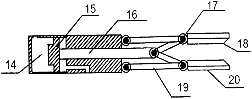
[0027] (3) When starting to work, the rotary cylinder 13 moves to the specified position, stops, the telescopic cylinder ①1 moves, and reaches a certain position, then the telescopic cylinder ②3 moves, the mechanical claw descends, and the telescopic cylinder ③14 starts to move to a certain position. Air, the gripper 20 opens, then grabs the item, grabs the item, then the telescopic cylinder ②3 moves, the mechanical claw rises, and rises until the m...


PUM


Abstract

The movable pneumatic manipulator comprises a mechanical claw linkage part and a mechanical claw, and the mechanical claw linkage part is provided with a wheel support, wheels, a bearing chassis, a rotating bearing, an air cylinder fixing frame, a rotating air cylinder, a telescopic air cylinder, a supporting frame, a limiting switch, a mechanical claw fixing frame and a telescopic arm; the mechanical claw is provided with a telescopic air cylinder, a piston, a power shaft, a mechanical claw movable arm connecting shaft, an elastic gasket, a clamping claw and a mechanical claw movable arm. And the PLC is used for writing programs to control different air cylinders, corresponding actions are carried out to take and place objects, the using effect is obvious, and good market application prospects are achieved.

Description

technical field [0001] The invention relates to the technical field of pneumatic manipulators, in particular to a movable pneumatic manipulator. Background technique [0002] Usually, when there are few items to be moved, a small amount of manpower can meet the demand, but when there are a lot of items to be moved, a small amount of manpower can no longer meet the demand, and the work efficiency is low. At this time, more manpower needs to be invested , an invisible increase in part of the cost. In addition, when the working environment is relatively harsh and the environment is relatively harmful to human health, if manpower is invested at this time, it will be very unfriendly to human life and health. Therefore, enterprises attach great importance to the use of manipulators, and have developed in many fields, such as handling manipulators, refining manipulators, etc. The use of these manipulators saves costs for enterprises and improves work efficiency, and it also indir...

Claims


Application Information

Patent Timeline
IPC IPC(8): B25J15/08B25J15/02
CPCB25J15/08B25J15/0253B25J15/0023
Inventor 袁臣虎闫园
Owner TIANJIN POLYTECHNIC UNIV
Why Eureka
Try Eureka