Automatic cutting device for production of triangular belt of oil pumping unit

A technology of automatic cutting device and V-belt, which is applied in the direction of metal processing, etc., can solve the problems of irregular cutting edges, incorrect position placement, and reserved V-belt sleeves, and achieve the effect of preventing position deviation.

Active Publication Date: 2022-03-04
胜利油田长龙橡塑有限责任公司
View PDF12 Cites 1 Cited by
  • Summary
  • Abstract
  • Description
  • Claims
  • Application Information

AI Technical Summary

Problems solved by technology

[0003] During the production and processing of the existing V-belts, it is often necessary to cut the circular wide-width V-belts into several circular small V-belts with the same or different widths. However, in the process of using the existing cutting equipment, since the V-belts are It is set on the transmission shaft or roller for cutting, so the V-belt is easy to deviate from the position during cutting, causing the V-belt to be easily cut crookedly, and may also cause the cutting edge to be irregular
In addition, the existing cutting mechanism does not reserve enough space for the V-belt to be set, which may cause the V-belt to be placed incorrectly due to the narrow space when the V-belt is set, thus cutting the V-belt crookedly.

Method used


Image

  • Automatic cutting device for production of triangular belt of oil pumping unit
  • Automatic cutting device for production of triangular belt of oil pumping unit
  • Automatic cutting device for production of triangular belt of oil pumping unit

Examples


Embodiment

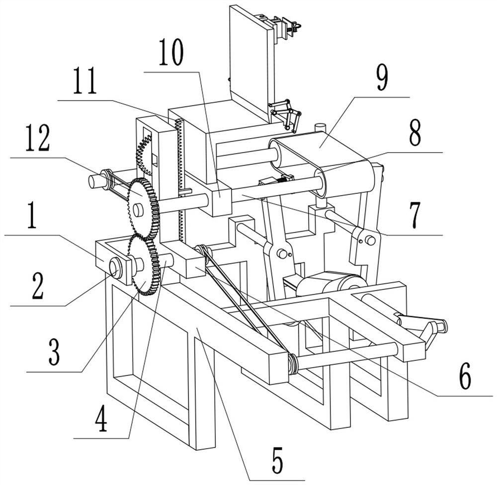
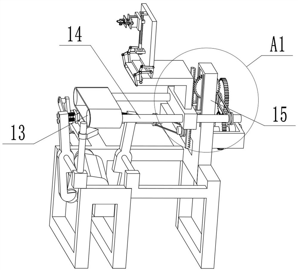
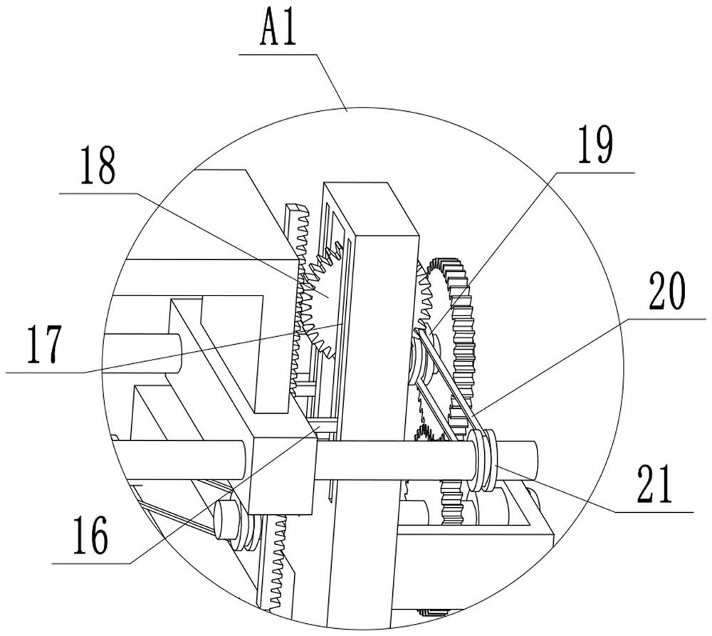
[0033] Example: Figure 1 - Figure 16 Pumping Unit production belt illustrated automatic cutting apparatus, a small bracket fixedly mounted on the holder 15 is placed, it is placed on a holder 15 fixedly mounted transfer holder 5, the active force of the motor 2 is fixedly mounted in a small holder 1, the main gear 3 is fixedly mounted on the main shaft 4, main shaft 4 is fixedly mounted on the output shaft of the active force of the motor 2, a main shaft 4 rotatably installed on the main mount 6, the main mount 6 is fixedly mounted in a fixed place 15, a first rotatably mounted lever 7 is placed on the placement base 10 is placed on the holder 10 is placed is fixed with a rack 11 is mounted, is placed with a seat 10 fixedly mounted on the slide bar 16 is placed, is placed in the slide bar 16 slidably mounted carriage disposed groove 17, the chute 17 is placed on the holder 15 is placed is provided, a first roller 8 is fixedly mounted on the first lever 7 is placed, the second leve...


PUM


Abstract

The invention discloses an automatic cutting device for pumping unit triangular belt production, and mainly relates to the technical field of triangular belt production, the automatic cutting device comprises a placing mechanism and a positioning mechanism, the placing mechanism is slidably mounted on a fixing frame, a power assembly is arranged on the fixing frame, and the placing mechanism is used for sleeving a cut triangular belt and is driven by the power assembly; a plate turning mechanism is installed on the placing mechanism, the plate turning mechanism can reserve enough space for sleeving the triangular belt, a cutting mechanism is installed on the plate turning mechanism in a sliding mode, the cutting mechanism comprises a cam assembly and a cutting knife, and the cam assembly enables the cutting knife to intermittently cut the triangular belt; the positioning assembly can drive the closing claw assembly to do opening and closing movement through the moving assembly to position the triangular belt, and the transferring assembly is used for driving the moving assembly to change the opening and closing angle of the closing claw assembly so as to adapt to the triangular belts with different widths. According to the triangular belt cutting device, unqualified cutting caused by deviation of the position of the triangular belt can be prevented when the triangular belt is cut.

Description

Technical field [0001] The present invention mainly involves the field of triangular belt production, and in particular, an automatic cutting device for the production of anifeter tributary production. Background technique [0002] The triangle has two types of special belt structures and rope core structures, respectively consisting of a pack, a top glue, a tensile body and a bottom glue. The triangular manufacturing of the rope core structure is convenient, and the strength of tensile strength is general, the price is low, and widely used. The triangular toughness of the special belt-core structure is good, high strength, suitable for applications with high speed. The core of the special belt core triangular belt is made of a high molecular polyester tempered brown wire consolidated strip-shaped core structure. Since the polyester tempered brown wire is the whole solid core, the adhesion is good, the sound resistance, the strength is high, not only the long increase of the life...

Claims


Application Information

Patent Timeline
Patent Type & Authority Applications(China)
IPC IPC(8): B26D1/16B26D5/16B26D7/26B26D7/01
CPCB26D1/165B26D5/16B26D7/2635B26D7/015
Inventor 穆学杰王心金柳玉功肖志强缪东迎张义贵马雨窦钦谭李艳顺
Owner 胜利油田长龙橡塑有限责任公司
Why Eureka
Try Eureka