Liquid storage device, vertical scroll compressor and refrigeration cycle system

A liquid storage device, vertical technology, applied in compressors, compressors, compressors with irreversible cycles, etc., can solve the problems of large gas flow resistance and low energy efficiency, and achieve the effect of less suction superheat and high energy efficiency

Pending Publication Date: 2022-03-04
GUANGDONG MIDEA ENVIRONMENTAL TECH CO LTD
View PDF0 Cites 0 Cited by
  • Summary
  • Abstract
  • Description
  • Claims
  • Application Information

AI Technical Summary

Problems solved by technology

[0003] The purpose of the embodiments of the present application is to provide a liquid storage device, a vertical scroll compressor, and a refrigeration cycle system, aiming to solve the problem of low energy efficiency caused by large gas flow resistance during the refrigeration cycle

Method used


Image

  • Liquid storage device, vertical scroll compressor and refrigeration cycle system
  • Liquid storage device, vertical scroll compressor and refrigeration cycle system
  • Liquid storage device, vertical scroll compressor and refrigeration cycle system

Examples


Embodiment 1

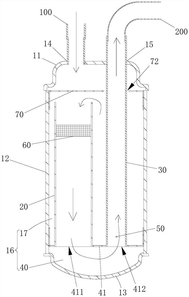
[0039] like figure 2 As shown, Embodiment 1 of the present invention provides a liquid storage device. Specifically, the liquid storage device includes a housing, a first delivery pipe 20, a second delivery pipe 30 and a buffer chamber 40. When specifically designed and assembled, the housing has a cavity 16, and the upper part of the housing is provided with an input port 14 and a buffer chamber 40. Output port 15, one of input port 14 and output port 15 is an air inlet, and the other of the two is an air outlet (in embodiment one, input port 14 is used as an air inlet, and output port 15 is used as an air outlet) , And, the lower part of the housing is provided with a buffer chamber 40 . The first delivery tube 20 is located in the cavity 16, the second delivery tube 30 is located in the cavity 16, the end of the first delivery tube 20 towards the top of the cavity is an open end, and the end of the first delivery tube 20 towards the bottom of the cavity 16 The other end ...

Embodiment 2

[0057] Compared with the liquid storage device of the first embodiment, the liquid storage device of the second embodiment has the following differences.

[0058] Such as Figure 5 As shown, one of the input port 14 and the output port 15 is opened on the top shell 11 , and the other of the input port 14 and the output port 15 is opened on the side shell 12 . In the liquid storage device of the second embodiment, the input port 14 is an air inlet, and the output port 15 is an air outlet. The opening at the end is higher than the air inlet, therefore, the gaseous refrigerant blown into the cavity 16 from the air inlet will first contact the wall of the first conveying pipe 20 and / or the second conveying pipe 30, and the gaseous refrigerant will carry The droplets will adhere to the tube wall of the first delivery tube 20 and / or the second delivery tube 30, and then the droplets will converge and fall along the tube wall to the bottom of the liquid storage chamber 17 for storag...

Embodiment 3

[0061] Compared with the liquid storage device of the first embodiment, the liquid storage device of the third embodiment has the following differences.

[0062] Such as Image 6 As shown, one of the input port 14 and the output port 15 is opened on the top shell 11 , and the other of the input port 14 and the output port 15 is opened on the side shell 12 . In the liquid storage device of the third embodiment, the input port 14 is an air inlet, and the output port 15 is an air outlet. end and the air inlet are staggered from each other, preventing the gaseous refrigerant entering the cavity 16 from the air inlet of the top case 11 from directly flowing into the opening end of the first conveying pipe 20, that is, preventing the liquid droplets carried by the gaseous refrigerant from directly entering The open end of the first delivery pipe 20 enters the compression chamber of the vertical scroll compressor to generate liquid hammer.

[0063] Such as Image 6 with Figure 7...


PUM


Abstract

The invention belongs to the technical field of refrigeration engineering, and particularly relates to a liquid storage device, a vertical scroll compressor and a refrigeration cycle system. The liquid storage device comprises a shell, the shell is provided with a cavity, the upper portion of the shell is provided with an input port and an output port, and the lower portion of the shell is provided with a buffer cavity; the first conveying pipe is located in the cavity, the end, facing the top of the cavity, of the first conveying pipe is an open end, and the other end, facing the bottom of the cavity, of the first conveying pipe communicates with the buffer cavity; and the second conveying pipe is located in the cavity, the end, facing the top of the cavity, of the second conveying pipe communicates with the output port, and the other end, facing the bottom of the cavity, of the second conveying pipe communicates with the buffer cavity. By applying the technical scheme of the embodiment of the invention, the problems of relatively low energy efficiency and relatively large gas flow noise caused by large gas flow resistance loss in the refrigeration cycle process are solved.

Description

technical field [0001] The application belongs to the technical field of refrigeration engineering, and in particular relates to a liquid storage device, a vertical scroll compressor and a refrigeration cycle system. Background technique [0002] like figure 1 As shown, in the prior art, the air inlet 301 of the vertical scroll compressor 300 is located on the upper part of the casing of the vertical scroll compressor 300, and the air outlet 303 of the liquid storage device 302 is also arranged on the liquid storage device 302 The lower part of the housing, the liquid storage device 302 and the vertical scroll compressor 300 are connected to each other through a pipeline 304, a part of the pipeline 304 extends into the inside of the liquid storage device 302, and the pipeline 304 faces the side of the liquid storage device 302 One end of the upper part is an air inlet, in order to prevent the liquid droplets carried in the gaseous refrigerant from directly entering the pipe...

Claims


Application Information

Patent Timeline
Patent Type & Authority Applications(China)
IPC IPC(8): F25B43/00F25B31/00F25B41/40F25B1/04
CPCF25B43/006F25B31/00F25B41/40F25B1/04
Inventor 谭琴李伟东罗承卓
Owner GUANGDONG MIDEA ENVIRONMENTAL TECH CO LTD
Why Eureka
Try Eureka