
Eureka
For R&D, Eureka makes reading and utilizing patents & technical documents easy.
Eureka AIR
Designed for self-driven R&D workflows. Generate viable solutions, solve complex R&D challenges, empower your innovation with AI.

Eureka Materials
Designed for material experts only. Revolutionize your material R&D, from search, analyze, to developing new materials.

TechResearch
Generate reliable direction feasibility study reports for your R&D in just a few steps.

TechSeek
Discover and master advanced knowledge NOW. Basics, ideas, possibilities, all at once.

TechMind
As an expert in R&D Theories, TechMind can generates customized viable solutions instantly.

TechRisk
Analyze your overall solution with one click, know your potential R&D risks in advance.

TechMonitor
Get weekly tech updates, stay abreast of the latest tech innovations and key insights.
Wafer drying system and wafer drying method
A wafer drying and wafer technology, which is applied in drying chamber/container, drying solid material, drying gas arrangement, etc., can solve the high risk of secondary contamination, low applicability of high-end process, and uncontrollable air turbulence in space and other issues, to achieve the effect of reducing the risk of secondary contamination, small impact damage, and small impact effect
- Summary
- Abstract
- Description
- Claims
- Application Information
AI Technical Summary
Problems solved by technology
Method used
Image

Examples
Embodiment 1
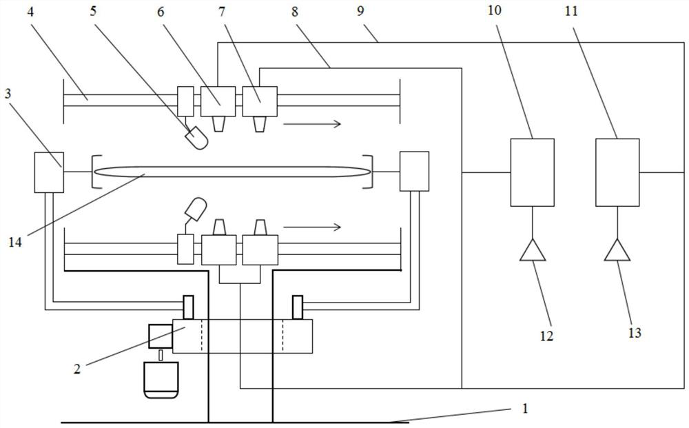
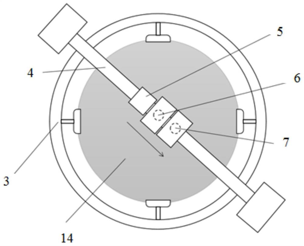
[0026] refer to Figure 1-Figure 2 , the present embodiment provides a wafer drying system, comprising:
[0027] Rotary double-sided gradient drying device; rotary double-sided drying device includes:
[0028] The spin chuck 3 is adapted to fix the wafer 14 from the side for horizontal rotation.
[0029] The gradient drying assembly includes an upper assembly and a lower assembly, and the rotary chuck 3 is located between the upper assembly and the lower assembly. The gradient drying component is suitable for performing gradient drying on the wafer from the upper and lower sides simultaneously when the wafer is rotating horizontally.
[0030] The wafer drying system provided in this embodiment can fix the wafer 14 to rotate horizontally through the rotary chuck 3, and at the same time, gradient drying components are arranged on the upper side and the lower side, and the gradient drying can be performed on the upper and lower sides of the wafer at the same time. The horizont...
Embodiment 2
[0041] refer to Figure 1 ~ Figure 3 , This embodiment provides a wafer drying method, using the wafer drying system provided in Embodiment 1 above to perform synchronous rotary gradient drying on the upper and lower sides of the wafer.
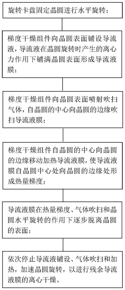
[0042] Among them, the rotary chuck fixes the wafer to rotate horizontally; the gradient drying component performs gradient drying from the center of the wafer to the edge of the wafer.
[0043] Specifically, the steps of gradient drying include:
[0044] The gradient drying component lays a diversion liquid on the surface of the wafer, and the diversion liquid covers the surface of the wafer under the action of the centrifugal force generated when the wafer rotates to form a diversion liquid film.
[0045] The gradient drying component sprays purge gas to the surface of the wafer, and purges the diversion liquid film from the center of the wafer to the edge of the wafer.
[0046] The gradient drying component moves the heated diversion liq...
PUM
 Abstract
Description
Claims
Application Information
 - R&D Engineer
- R&D Manager
- IP Professional
- Industry Leading Data Capabilities
- Powerful AI technology
- Patent DNA Extraction
Browse by: Latest US Patents, China's latest patents, Technical Efficacy Thesaurus, Application Domain, Technology Topic, Popular Technical Reports.
© 2024 PatSnap. All rights reserved.Legal|Privacy policy|Modern Slavery Act Transparency Statement|Sitemap|About US| Contact US: help@patsnap.com