Tire limiter for automobile detection
A technology of stopper and tire, applied in the direction of vehicle testing, instruments, measuring devices, etc., can solve the problem that the driver cannot accurately judge the positioning point, the detection equipment is inconvenient for car detection, and the distance between the wheel and the block cannot be detected.
- Summary
- Abstract
- Description
- Claims
- Application Information
AI Technical Summary
Problems solved by technology
Method used
Image

Examples
Embodiment 1
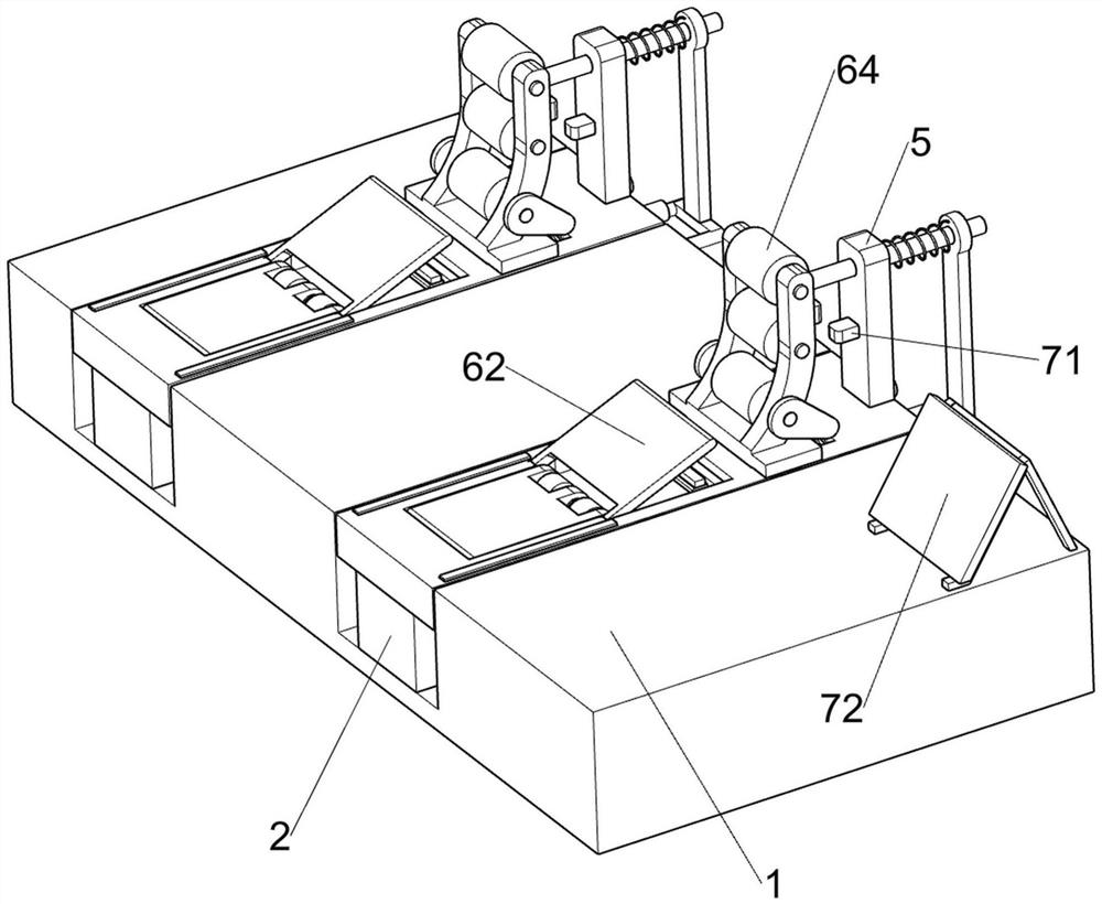
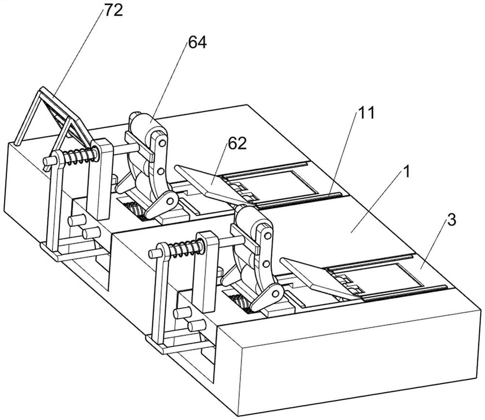
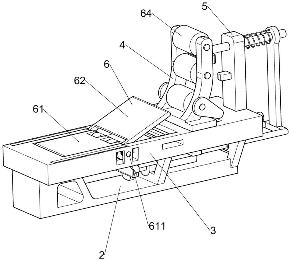
[0034] A tire stopper for automobile detection, such as figure 1 , figure 2 , image 3 , Figure 4 , Figure 5 , Image 6 and Figure 7 As shown, it includes an installation frame 1, a base 2, a limit bottom plate 3, a sliding buffer frame 4, a fixed seat 5, a buffer limit assembly 6, a distance display assembly 7 and a tire front limit assembly 8, and the installation frame 1 is fixedly installed There are two bases 2, the top surface of the base 2 is fixed with a limit base plate 3, the limit base plate 3 is slidably connected with a sliding buffer frame 4, the fixed seat 5 is fixedly connected to the top surface of the limit base plate 3, and the buffer limit assembly 6 is located on On the limit base plate 3, the buffer limit assembly 6 is used for buffering the rear wheels of the automobile, and the distance display assembly 7 is fixedly installed on the front side of the fixed seat 5, and the distance display assembly 7 is used to detect the distance between the re...
Embodiment 2
[0041] On the basis of Example 1, such as Figure 7 As shown, it also includes a rear tire limit reinforcement assembly 9, which is arranged on the fixed groove seat 83, and the rear tire limit reinforcement assembly 9 is used to enhance the resistance applied to the rear wheels of the car. The rear position limit reinforcement assembly 9 includes a fixed slide bar 91, a fixed slide seat 92 and an extruding spring 93. The fixed slide bar 91 is fixedly connected to the fixed groove seat 83, and the fixed slide bar 91 is slidably connected with the base 2. The top of the rod 91 is slidably connected with a fixed slide 92, the fixed slide 92 is slidably connected with the fixed base 5, the fixed slide 92 is fixedly connected with the sliding buffer frame 4, and the fixed slide 92 is covered with an extrusion spring 93. The spring 93 is used to buffer the fixed slide 92 and its upper device. One end of the extrusion spring 93 is in contact with the fixed slide 92, and the other en...
Embodiment 3
[0044] On the basis of Example 1, such as Figure 7 As shown, it also includes a side limit eccentric disc 10, and the two ends of the bottom movable pulley 64 are fixedly connected with the side limit eccentric disc 10, and the side limit eccentric disc 10 is used to block the rear wheel of the automobile.
[0045] When the movable pulley 64 was in contact with the rear wheel of the automobile, the rear wheel of the automobile would rotate clockwise because the automobile was reversing. The rear wheel is stuck, and the rear wheel of the car is further limited.
PUM
 Abstract
Description
Claims
Application Information
 - R&D
- Intellectual Property
- Life Sciences
- Materials
- Tech Scout
- Unparalleled Data Quality
- Higher Quality Content
- 60% Fewer Hallucinations
Browse by: Latest US Patents, China's latest patents, Technical Efficacy Thesaurus, Application Domain, Technology Topic, Popular Technical Reports.
© 2025 PatSnap. All rights reserved.Legal|Privacy policy|Modern Slavery Act Transparency Statement|Sitemap|About US| Contact US: help@patsnap.com