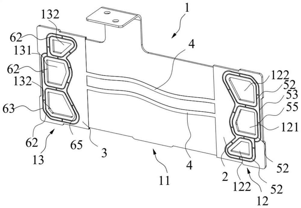
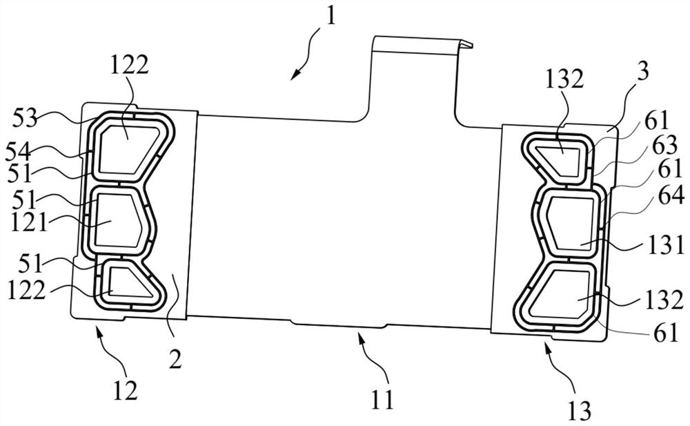
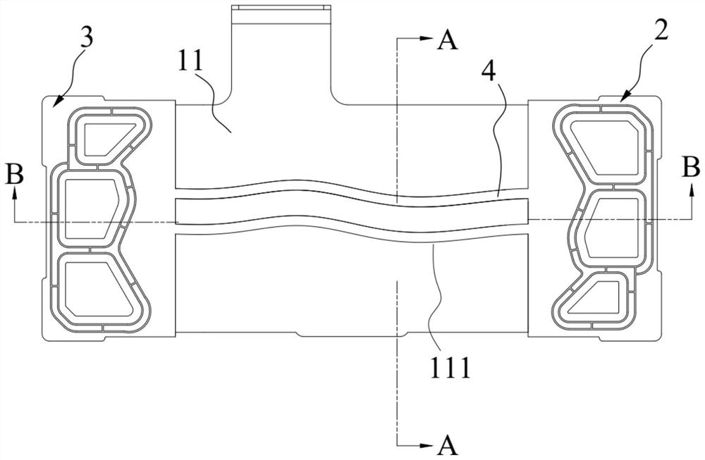
Collector plate

A collector plate and flow channel technology, applied in the field of collector plates, can solve the problems of preventing the heat dissipation of the collector plate and thermal runaway of the collector plate, so as to prevent heat dissipation failure and improve work efficiency

Pending Publication Date: 2022-03-04
CHINA AUTOMOTIVE INNOVATION CORP
View PDF8 Cites 0 Cited by
  • Summary
  • Abstract
  • Description
  • Claims
  • Application Information

AI Technical Summary

Problems solved by technology

[0004] The purpose of the present invention is to provide a current collecting plate to solve the problem in the related art that after the current collecting plate is wrapped by the plastic casing, the heat dissipation of the current collecting plate will be prevented, and the thermal runaway of the current collecting plate will easily be caused.

Method used


Image

  • Collector plate
  • Collector plate
  • Collector plate

Examples


Embodiment Construction

[0040] The technical solutions of the present invention will be clearly and completely described below in conjunction with the accompanying drawings. Apparently, the described embodiments are some of the embodiments of the present invention, but not all of them. Based on the embodiments of the present invention, all other embodiments obtained by persons of ordinary skill in the art without making creative efforts belong to the protection scope of the present invention.

[0041]In the description of the present invention, it should be noted that the terms "center", "upper", "lower", "left", "right", "vertical", "horizontal", "inner", "outer" etc. The indicated orientation or positional relationship is based on the orientation or positional relationship shown in the drawings, and is only for the convenience of describing the present invention and simplifying the description, rather than indicating or implying that the referred device or element must have a specific orientation, o...


PUM


Abstract

The present invention relates to the technical field of fuel cells, and particularly discloses a collector plate, the collector plate comprises a collector plate body, a first coating layer and a second coating layer, the first coating layer and the second coating layer respectively coat the outer surface of a first connection area and the outer surface of a second connection area of the collector plate body, the first coating layer is provided with a first cooling cavity, and the second coating layer is provided with a second cooling cavity. The first coating layer is provided with a first cooling cavity, the second coating layer is provided with a second cooling cavity, the first cooling cavity is communicated with the second cooling cavity through a flow channel, the first liquid inlet and outlet is communicated with the first cooling cavity, the second liquid inlet and outlet is communicated with the second cooling cavity, and cooling liquid enters the first cooling cavity through the first liquid inlet and outlet and then enters the second cooling cavity through the flow channel. Finally, the cooling liquid in the second cooling cavity flows into the second liquid inlet and outlet. The first cooling cavity and the second cooling cavity are respectively used for cooling the first connecting area and the second connecting area, and the reaction area is directly exposed in the air. The collector plate can take away heat generated by the collector plate in time, and thermal failure of the collector plate is prevented.

Description

technical field [0001] The invention relates to the technical field of fuel cells, in particular to a collector plate. Background technique [0002] As a new type of energy conversion device, fuel cell has rapidly attracted people's attention in related fields due to its advantages of high energy conversion rate, high reliability, high cleanliness, and no noise. A fuel cell consists of a membrane electrode, a bipolar plate, a collector plate and an end plate connecting several single cells in series. The collector plate is one of the important components of the fuel cell, which not only requires good conductivity and flexibility, but also requires It has excellent resistance to electrochemical corrosion. [0003] Patent application number 202010076638.9 discloses a plastic-coated collector plate and a fuel cell, which includes a collector plate body and a plastic-coated shell, the central area of ​​the collector plate body is set as a reaction zone, and the plastic-coated s...

Claims


Application Information

Patent Timeline
Patent Type & Authority Applications(China)
IPC IPC(8): H01M8/0202H01M8/0258H01M8/0267H01M8/0271H01M8/0276
CPCH01M8/0202H01M8/0258H01M8/0267H01M8/0271H01M8/0278Y02E60/50
Inventor 王英刘冬安何海楠宋强刘威
Owner CHINA AUTOMOTIVE INNOVATION CORP
Why Eureka
Try Eureka