Line layout method based on assembly type line pipe fittings

A line layout and assembly technology, which is applied in the direction of electrical components, cable installation, cable installation devices, etc., can solve the problems of relatively high professional requirements for bending pipes, smaller diameters of pipe bends, and increased difficulty of bending pipes, etc. , to achieve the effect of improving construction efficiency, reducing construction strength and convenient installation

Pending Publication Date: 2022-03-04
LINHAI WEIXING NEW BUILDING MATERIALS CO LTD
View PDF3 Cites 0 Cited by
  • Summary
  • Abstract
  • Description
  • Claims
  • Application Information

AI Technical Summary

Problems solved by technology

At the corner of the pipeline, a special pipe bender will be used together with a special pipe bending process for processing, so that the pipe bending requires relatively high professionalism, and the pipe bending process through the pipe bending spring will often lead to pipe bending The diameter at the place becomes smaller, which increases the difficulty of bending the pipe to a certain extent, while the traditional threading operation takes a long time and is difficult to operate

Method used


Image

  • Line layout method based on assembly type line pipe fittings
  • Line layout method based on assembly type line pipe fittings
  • Line layout method based on assembly type line pipe fittings

Examples


Embodiment 1

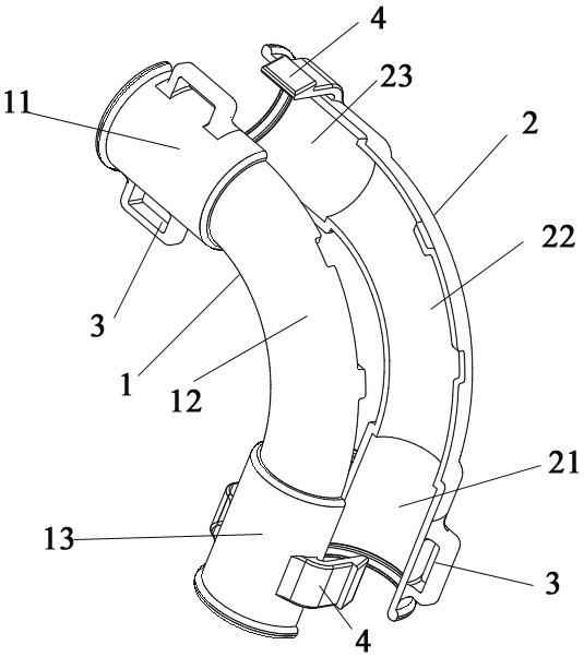
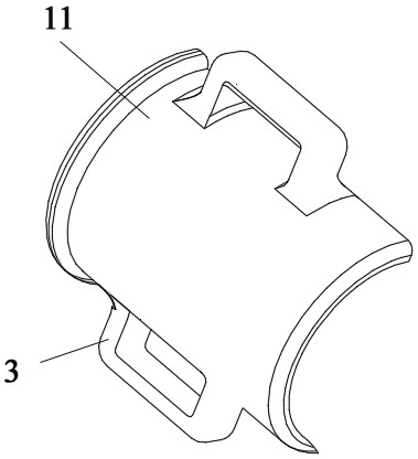
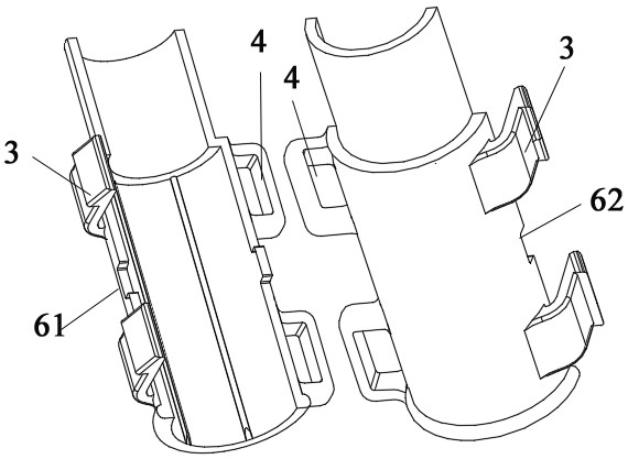
[0027] The socket conduit includes a first connecting piece 1 and a second connecting piece 2, the first connecting piece 1 and the second connecting piece 2 have the same structure, as figure 1 In the structure shown, the first connecting piece 1 is integrally formed, including the first elbow portion 11, the first connecting pipe portion 12 and the first bent tail portion 13, and the second connecting piece 2 is integrally formed, including the second elbow portion 21, The second connecting pipe part 22 and the second bent tail part 23, two snap rings 3 are arranged on the outer sides of the first bent tail part 11, two plug-ins 4 are arranged on the outer sides of the first bent tail part 13, and the second bent tail part 13 is provided with two snap rings 3 on both sides. Two snap rings 3 are provided on the outer sides of the head 21 for inserting the inserter 4 of the first bent tail 13, and two inserts 4 are arranged on the outer sides of the second bent tail 23 for inse...

Embodiment 2

[0029] The connecting pipe includes a first elbow 11, a first elbow 13, a second elbow 21, a second elbow 23 and a first connecting pipe 12, the first connecting pipe 12 is integrally formed, as figure 2 As shown, two snap rings 3 are provided on both sides of the first elbow 11, two inserts 4 are provided on both sides of the first elbow 13, and two outer sides of the second elbow 21 are provided. Two snap rings 3 are provided on the outside of the second bent tail 23, the first bent head 11 and the second bent tail 23 are snapped together to form a buckle cavity at the head end, and the second bent head 21 is connected to the first bent tail 23. The tail part 13 is clamped to form a terminal buckle cavity, and the head-end buckle cavity and the end buckle cavity are respectively buckled at both ends of the connecting pipe body.

Embodiment 3

[0031] The receiving pipeline includes a first connecting piece 1 and a second connecting piece 2. The first connecting piece 1 is integrally formed, including a first elbow portion 11, a first connecting pipe portion 12 and a first bent tail portion 13. The second connecting piece 2 is integrally formed. Forming, including the second elbow part 21, the second connecting pipe part 22 and the second bent tail part 23, the outer two sides of the first elbow part 11 are provided with a snap ring 3 and a plug-in 4, the first bent tail part 13 A plug-in 4 and a snap ring 3 are provided on the outside, and a snap ring 3 and a plug-in 4 are provided on both sides of the second elbow 21 for inserting the plug-in 4 and the snap ring 3 of the first elbow 11 There are two inserts 4 on both sides of the outside of the second curved tail 23, which are used to insert the snap ring 3 and the plug 4 of the first curved tail 13, and the first connecting pipe part 12 and the second connecting pi...


PUM


Abstract

The invention discloses a line layout method based on an assembly type line pipe fitting, a line pipe assembly is included, the line pipe assembly comprises a straight line pipe and a bearing line pipe, the two ends of the bearing line pipe are used for bearing the straight line pipe, and the line layout method comprises the following steps that according to a construction drawing, line groove slotting in a wall body (including the bottom face) is completed; according to the specification and the size of the wire duct, cutting of the straight wire pipe is completed; the corner position is marked, the bearing line pipe is selected at the corner position to complete bearing, the bearing line pipe is directly connected with the straight line pipe or connected with the straight line pipe through a clamping structure, and the clamping structure is used for filling errors caused during cutting. The bearing pipeline comprises a first connecting piece and a second connecting piece, and a head end buckling cavity and a tail end buckling cavity are formed after the first connecting piece and the second connecting piece are in butt joint and used for buckling a straight line pipe. According to the invention, the installation of the wire at the bent pipe is more convenient, the construction intensity of workers can be effectively reduced, the efficiency is improved, and the later threading process is omitted in the whole construction process.

Description

technical field [0001] The invention belongs to the technical field of wiring and pipeline layout, and in particular relates to a wiring layout method based on assembled wiring and pipe fittings. Background technique [0002] With the development of new building technologies, prefabricated buildings are getting more and more attention from the government and real estate developers. The assembly rate of the project has also become a rigid assessment index of the building. [0003] Like prefabricated buildings, prefabricated interiors advocate the improvement of construction efficiency and the reduction of construction energy consumption. The electrical system in the traditional prefabricated building interior system is generally installed in the traditional way: positioning - slotting - pipe routing - threading. At the corner of the pipeline, a special pipe bender will be used together with a special pipe bending process for processing, so that the pipe bending requires rel...

Claims


Application Information

Patent Timeline
Patent Type & Authority Applications(China)
IPC IPC(8): H02G3/04H02G3/06H02G1/00
CPCH02G3/0481H02G3/06H02G1/00
Inventor 叶伟东朱海强方升霍福磊
Owner LINHAI WEIXING NEW BUILDING MATERIALS CO LTD
Why Eureka
Try Eureka