Uterus grasping forceps and electric hysterectomy device

A technology for hysterectomy and uterus implantation, which is applied to surgical cutting instruments, surgical forceps, and obstetrics and gynecology instruments, etc., can solve the problems of affecting the field of vision of operators, increasing patient damage, and easily damaged cutter heads, so as to improve cutting safety. , Improve the accuracy of judgment and avoid the effect of contact damage

Pending Publication Date: 2022-03-08
ZHEJIANG SHENDASIAO MEDICAL INSTR
View PDF1 Cites 0 Cited by
  • Summary
  • Abstract
  • Description
  • Claims
  • Application Information

AI Technical Summary

Problems solved by technology

However, in the actual operation process, due to the narrow operating space and the extrusion of external organs, the cutting head of the resection knife tube is easy to contact with external organs during rotary cutting, resulting in frictional damage to external organs
On the other hand, the tissue will spray a lot of blood during the cutting process, causing the blood to accumulate around the cutter head and affect the operator's vision
The current solution to this problem is to insert a suction device on one side of the electric hysterectomy device, and the blood accumulation at the cutter head will be sucked out by the suction device, but this method will undoubtedly increase the damage to the patient. For the narrow internal space, it is difficult to realize suction and cutting and grabbing operations at the same time, and there is some interference during suction
[0005] Therefore, the existing electric hysterectomy device has the problems that the cutter head is easily damaged, the safety of resection is low, and the fresh blood generated during resection is difficult to suck away.

Method used


Image

  • Uterus grasping forceps and electric hysterectomy device
  • Uterus grasping forceps and electric hysterectomy device
  • Uterus grasping forceps and electric hysterectomy device

Examples


Embodiment Construction

[0037] The present invention will be further described below in conjunction with the accompanying drawings and embodiments, but not as a basis for limiting the present invention.

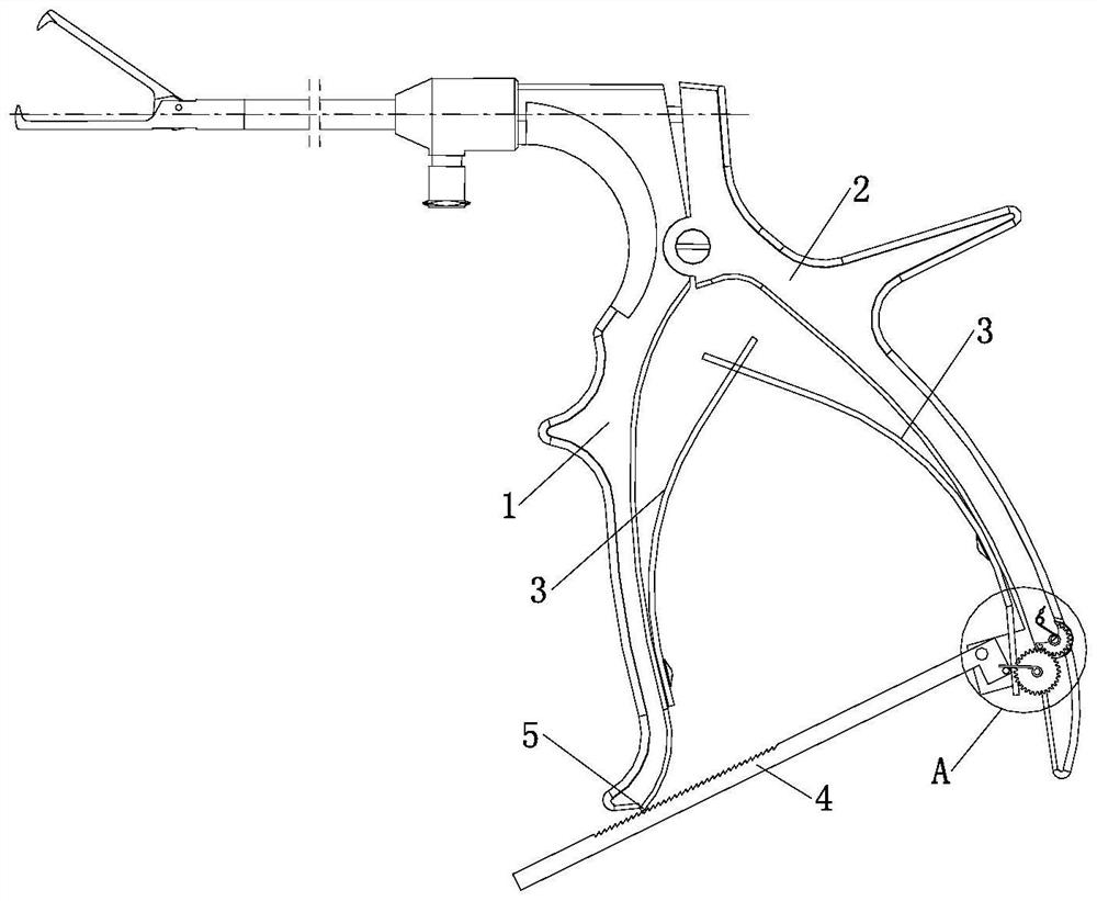
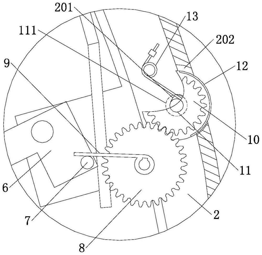
[0038] Example. A uterine grasping forceps constituted as Figure 1-2 As shown, it includes a fixed pliers handle 1 and a movable pliers handle 2 that are rotationally connected, and a spring leaf 3 is provided on the inner side of the fixed pliers handle 1 and the movable pliers handle 2, and the spring leaves 3 on both sides are engaged with each other at the ends, and the movable pliers handle The lower end of the rack 2 is rotatably connected with a rack 4, one end of the rack 4 fits with the spring leaf 3, the other end of the rack 4 extends below the fixed pliers handle 1 and meshes with the tooth block 5 at the bottom of the fixed pliers handle 1, The end of the rack 4 is connected to the movable clamp handle 2 through the mounting block 6, the mounting block 6 is provided with a driving rod...


PUM


Abstract

The uterus grasping forceps comprise a fixed forceps handle and a movable forceps handle which are rotationally connected, spring pieces are arranged on the inner side of the fixed forceps handle and the inner side of the movable forceps handle, the end portions of the spring pieces on the two sides are mutually buckled, the lower end of the movable forceps handle is rotationally connected with a rack, one end of the rack is attached to the spring pieces, and the other end of the rack is attached to the movable forceps handle. The other end of the rack extends to the position below the fixed clamp handle and is meshed with a tooth block at the bottom of the fixed clamp handle, the end of the rack is connected with the movable clamp handle through a mounting block, a driving rod is arranged on the mounting block, a driving accessory rotationally connected with the movable clamp handle is arranged on the outer side of the driving rod, and a display part is connected to the outside of the driving accessory. And the display part partially extends to the outer side of the movable clamp handle and is provided with a display strip. According to the uterus grasping forceps, the possibility that the knife head is damaged when the uterus grasping forceps are pulled out can be effectively reduced, the excision knife tube is prevented from making contact with external organs during excision operation, and hematocele suction removal of the excision part is achieved.

Description

technical field [0001] The invention relates to a uterine grasping forceps, in particular to a uterine grasping forceps and an electric hysterectomy device. Background technique [0002] In women's hysterectomy, it is often necessary to use a hysterectomy device to remove tissue in the uterus. The currently commonly used electric hysterectomy device is described in the patent 201922470627.4 "An electric hysterectomy device", which includes an electric handle connected to each other, a cutting knife tube, a puncture sleeve and a uterine grasping forceps. The working channel is established, and then the uterine grasping forceps pass through the resection knife tube and grab the tissue in the uterus. After grasping, the uterine grasper contacts the tissue with the cutting head of the resection knife tube, and then turns on the electric handle to drive the resection knife The tube rotates at a high speed in the working channel and cuts the tissue, so that the tissue and the org...

Claims


Application Information

Patent Timeline
Patent Type & Authority Applications(China)
IPC IPC(8): A61B17/42A61B17/3205A61B17/295
CPCA61B17/42A61B17/4241A61B17/3205A61B17/295A61B2017/4216A61B2217/005
Inventor 申屠琛
Owner ZHEJIANG SHENDASIAO MEDICAL INSTR
Why Eureka
Try Eureka