Waterway switching control mechanism, shower head and driving mechanism

A control mechanism and waterway switching technology, applied in the field of sanitary ware, can solve the problems of complex structure and high cost, and achieve the effect of compact structure, low cost and convenient installation

Pending Publication Date: 2022-03-08
XIAMEN SOLEX HIGH TECH IND CO LTD
View PDF9 Cites 0 Cited by
  • Summary
  • Abstract
  • Description
  • Claims
  • Application Information

AI Technical Summary

Problems solved by technology

Since there are two operating parts to drive the control mechanism and the switching mechanism respectively, there are disadvantages of complex structure and high cost

Method used


Image

  • Waterway switching control mechanism, shower head and driving mechanism
  • Waterway switching control mechanism, shower head and driving mechanism
  • Waterway switching control mechanism, shower head and driving mechanism

Examples


Embodiment 1

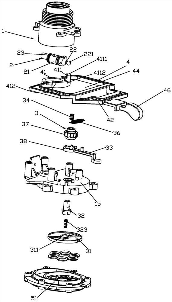
[0087] Waterway switching control mechanism, please refer to Figure 1 to Figure 9 , including the waterway part 1, the control mechanism 2, the switching mechanism 3 and the operation part 4.

[0088] The waterway part 1 includes a water inlet 11 and a three-way waterway 12 , the three-way waterway 12 is connected to the water inlet 11 . The waterway part 1 is concavely provided with an installation chamber 13 connected to the water inlet 11 , and the water inlet 11 is divided into two sections through the installation chamber 13 . The end of the water inlet 11 of the water channel part 1 is provided with a water distribution chamber 14, and the end of the water distribution chamber 14 is sealed and fixed with a fixed seat 15, and the bottom of the water distribution chamber 14 is provided with a water distribution port 121 of each water distribution channel 12.

[0089] The control mechanism 2 cooperates with the water inlet 11 to control the water inlet 11. The control inc...

Embodiment 2

[0102] Waterway switching control mechanism, please refer to Figure 11 to Figure 18 , it is different from Embodiment 1 in that: the rotation axis of the control part 4 is arranged parallel to the rotation axis of the rotary block 32; the operation part 4 has a fixed plate 47, and the end surface of the fixed plate 47 is concave-convex arranged to form the above-mentioned first driving part , the above-mentioned concave-convex structure is relatively perpendicular to the swing axis of the operating part; the penetrating area 44 is located at the rear of the operating part 4, and the control mechanism 2 is located at the front of the operating part 4. The layout is reasonable and the structure is compact. better. Please check Figure 19 , it is a shower that includes the above-mentioned water channel switching control mechanism, the shower is a hand shower, the hand shower is provided with two water outlets 51, and the three-way water channel 12 is respectively connected to t...

Embodiment 3

[0104] Waterway switching control mechanism, please refer to Figure 20 to Figure 28 , it is different from Embodiment 2 in that: the waterway part 1 includes three water distribution channels 12, the first water distribution channel is the first water outlet, the second water distribution channel is the second water outlet, and the third water distribution channel is the second water outlet. Water for the third. When the water stop is switched, the second driving member and the switching mechanism 3 are in linkage switching, and are not separated, that is, the function of the water stop switching process is also switching. When the function is switched, it is consistent with the previous two embodiments. The operation part 4 can be slidably connected to the waterway part 1 . The second driving part 42 is provided with a rack 48 that can be fixed relative to the operating part 4, and a gear 39 is fixed outside the rotary block 32, and the gear and the rack are engaged, so th...


PUM


Abstract

The invention discloses a waterway switching control mechanism, a shower head and a driving mechanism. The waterway switching control mechanism comprises a waterway part, a control mechanism, a switching mechanism and an operation part. The operating part can move relative to the waterway part and is provided with a first driving part and a second driving part, and the first driving part is provided with a control section and a self-locking section; the control section is matched with the control mechanism so as to movably drive the control mechanism through the operation part, and the control mechanism is driven at least to realize control; the second driving part is matched with the switching mechanism to movably drive the switching mechanism through the operating part, the switching mechanism is driven at least to realize switching, and the self-locking section is matched with the control mechanism to self-lock the control mechanism in at least partial process of driving the switching mechanism by the second driving part. The invention has the advantages that the waterway can be controlled and switched by a single operation part, the structure is simple, and the cost is low.

Description

technical field [0001] The invention relates to the technical field of sanitary ware, in particular to a waterway switching control mechanism, a shower and a driving mechanism. Background technique [0002] The existing waterway switching control mechanism includes a waterway part, a control mechanism, a switching mechanism, a first operating part, and a second operating part; the waterway part includes a water inlet and at least two branch waterways; Waterway, the control includes on-off or / and flow control; the switching mechanism cooperates with the water inlet and the water diversion to switch at least two water diversions to connect to the water inlet; the first operating part is connected to the control mechanism by transmission to drive the control mechanism Control is realized; the second operating part is connected to the switching mechanism by transmission so as to be able to drive the switching mechanism to realize switching. Since two operating parts are provide...

Claims


Application Information

Patent Timeline
Patent Type & Authority Applications(China)
IPC IPC(8): B05B1/18B05B1/16B05B1/30
CPCB05B1/18B05B1/16B05B1/30
Inventor 林逢德陈东海曹斌
Owner XIAMEN SOLEX HIGH TECH IND CO LTD
Why Eureka
Try Eureka