
Processing device

A technology for processing devices and workpieces, which is applied to fine working devices, stone processing equipment, grinding drive devices, etc., and can solve problems such as the inability to accurately detect and control the cutting depth of cutting tools into workpieces

Pending Publication Date: 2022-03-08
DISCO CORP
View PDF1 Cites 0 Cited by
  • Summary
  • Abstract
  • Description
  • Claims
  • Application Information

AI Technical Summary

Problems solved by technology

However, in reality, the relative positional relationship between the position of the light emitting unit and the light receiving unit and the position of the holding surface changes due to temperature fluctuations in the processing device, so there is a problem that it is impossible to accurately detect and The problem of controlling the cutting depth of the cutting tool into the workpiece

Method used


Image

  • Processing device
  • Processing device
  • Processing device

Examples


Embodiment approach 1

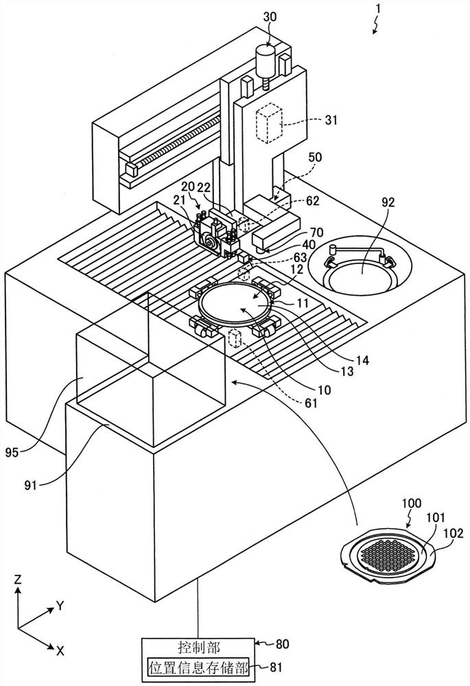
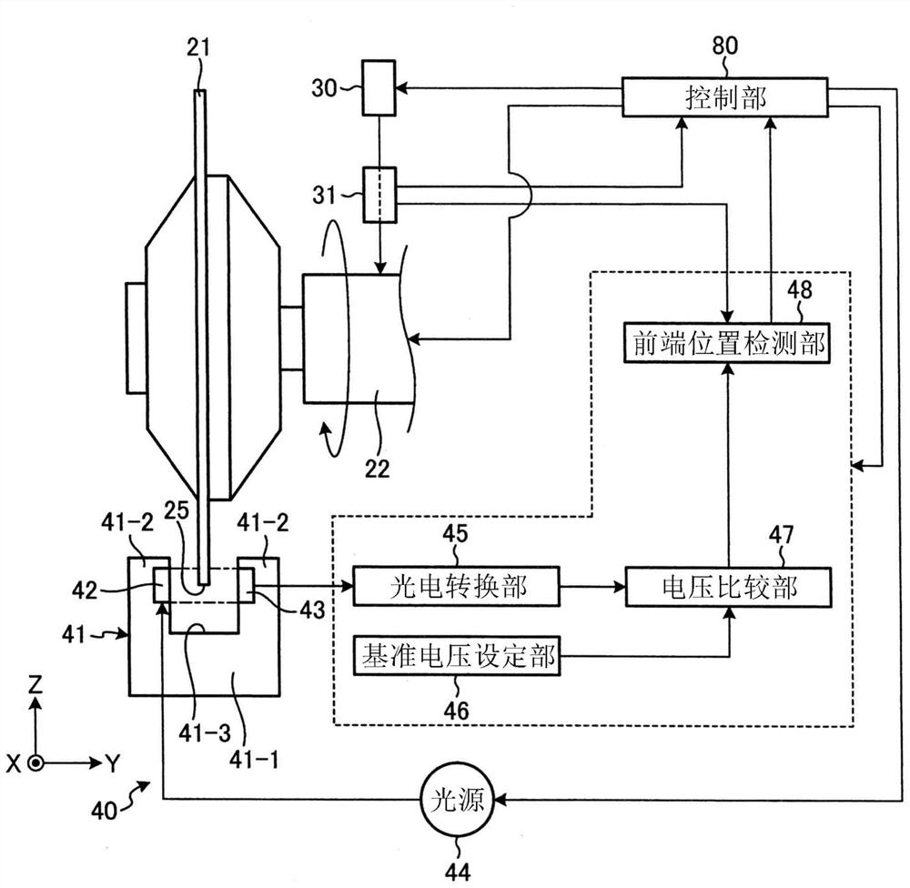
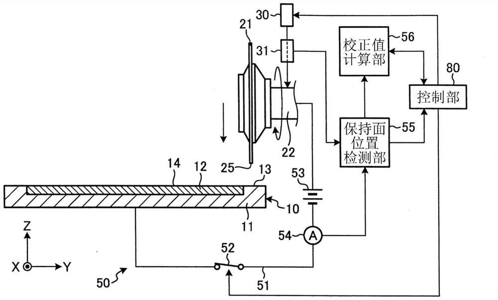
[0021] The processing apparatus 1 of Embodiment 1 of this invention is demonstrated based on drawing. figure 1 It is a perspective view showing a configuration example of the processing apparatus 1 according to the first embodiment. figure 2 is showing figure 1 A cross-sectional view of a structural example of the setting unit 40 . image 3 is showing figure 1 A cross-sectional view of a structural example of the correction unit 50. Figure 4 is showing figure 1 The sectional view of an example of the positional relationship of the holding table 10, the cutting unit 20, and the installation unit 40 of FIG.

[0022] Such as figure 1 As shown, the processing device 1 has a holding table 10 , a cutting unit 20 , a Z feed unit 30 , a setting unit 40 , a calibration unit 50 , temperature measuring devices 61 , 62 , and 63 , an imaging unit 70 , and a control unit 80 .

[0023] The workpiece 100 to be processed by the processing apparatus 1 according to Embodiment 1 is, for e...

Embodiment approach 2

[0070] The processing apparatus 1 according to Embodiment 2 of the present invention will be described. In the processing device 1 according to the second embodiment, the imaging unit 70 which moves integrally with the cutting unit 20 substantially implements the function of detecting the holding surface position Z2 performed by the calibration unit 50 in the first embodiment. Specifically, in Embodiment 2, the imaging unit 70 obtains from the Z-direction position detection unit 31 the upper surface 13 of the housing 11 of the holding table 10 that is on the same plane as the holding surface 14 to focus the imaging unit 70 . The position of the cutting unit 20 in the Z direction is obtained, and the obtained position of the cutting unit 20 in the Z direction is output to the control unit 80 .

[0071] Here, by considering the position difference between the cutting unit 20 and the imaging unit 70 in the Z direction, the height of the imaging unit 70 in the Z direction can be c...


PUM


Abstract

The invention provides a processing device which can accurately detect the depth of a cutting tool cutting into a processed object. The machining device (1) is provided with a setting unit (40) which detects the front end position (Z1) of the cutting tool (21) according to the light emitted by the light emitting part and received by the light receiving part; a correction means for detecting the holding surface position (Z2) and storing, as a correction value ([delta] Z), the difference between the tip position (Z1) of the cutting blade (21) detected by the setting means (40) and the holding surface position (Z2) in the Z direction; and a control unit. When the amount of variation of the temperatures (T1, T2, T3) measured by the temperature measuring devices (61, 62, 63) from an arbitrary time exceeds a threshold value, the control unit causes the operation of detecting the holding surface position (Z2) by the correction means and updating the correction value ([delta] Z), and the detection of the tip position (Z1) of the cutting blade (21) by the setting means (40) to be performed again.

Description

technical field [0001] The invention relates to processing devices. Background technique [0002] There is known a method of detecting a reference position when a cutting tool comes into contact with a holding surface of a holding table by energizing the cutting tool and the holding table (for example, refer to Patent Document 1). In addition, there is known a method in which a light-emitting unit and a light-receiving unit are provided at intervals of a cutting tool penetration width, and a reference position of the cutting tool is obtained by detecting the position of the tip of the cutting tool from the light received by the light-receiving unit (for example, Refer to Patent Document 2). [0003] Patent Document 1: Japanese Utility Model Registration No. 2597808 [0004] Patent Document 2: Japanese Patent No. 4590058 [0005] However, in the method of detecting by energizing the cutting tool and the holding table, since the cutting tool cuts the holding table, clogging...

Claims


Application Information

Patent Timeline
IPC IPC(8): B24B27/06B24B41/06B24B47/12B24B49/12B24B49/14B24B51/00H01L21/304
CPCB24B27/06B24B27/0683B24B47/12B24B49/12B24B51/00B24B49/14B24B41/068H01L21/304B28D5/0064B28D5/0082B28D5/022
Inventor 木佐贯诚
Owner DISCO CORP
Learn More