Valve needle guide structure, valve needle guide positioning method and injection mold

A guide structure, injection mold technology, applied in the valve needle guide structure and valve needle guide positioning method, in the field of injection molds, can solve the problems of increased production waste rate, unsmooth gate glue, and damage to the mold core gate, etc. It achieves the effect of low machining accuracy requirements, convenient and quick installation, and improved product yield

Pending Publication Date: 2022-03-08
EVERFINEST PRECISION MACHINERY SHENZHEN
View PDF0 Cites 1 Cited by
  • Summary
  • Abstract
  • Description
  • Claims
  • Application Information

AI Technical Summary

Problems solved by technology

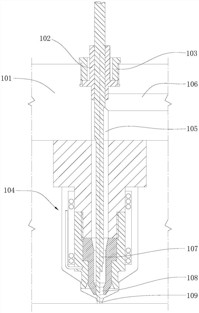
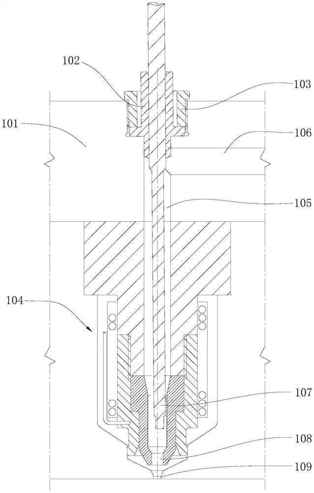
[0004] However, due to processing and assembly errors, it cannot be fully guaranteed that the central guide hole of the guide body 102 is on the same axis as the ejection hole 108 of the hot runner nozzle 104, such as figure 2 As shown, it is easy to cause the valve needle 107 to swing and damage the ejection hole 108 of the hot runner nozzle 104 during the movement, and even damage the gate 109 of the mold core, thereby affecting the surface appearance of the molded product, and the gate is too high and the gate Unsmooth gluing and other problems lead to increased production scrap rate, increased production costs and affect production efficiency

Method used


Image

  • Valve needle guide structure, valve needle guide positioning method and injection mold
  • Valve needle guide structure, valve needle guide positioning method and injection mold
  • Valve needle guide structure, valve needle guide positioning method and injection mold

Examples


Embodiment Construction

[0034] The following describes in detail the embodiments of the present invention, examples of which are illustrated in the accompanying drawings, wherein the same or similar reference numerals refer to the same or similar elements or elements having the same or similar functions throughout. The embodiments described below with reference to the accompanying drawings are exemplary, and are intended to be used to explain the present invention, but should not be construed as a limitation of the present invention. Based on the embodiments of the present invention, those of ordinary skill in the art do not make any creative work premise. All other embodiments obtained below belong to the protection scope of the present invention.

[0035] In the description of the present invention, it should be understood that the terms "center", "longitudinal", "lateral", "length", "width", "thickness", "upper", "lower", "front", " Back, Left, Right, Vertical, Horizontal, Top, Bottom, Inner, Oute...


PUM

PropertyMeasurementUnit
angleaaaaaaaaaa

Abstract

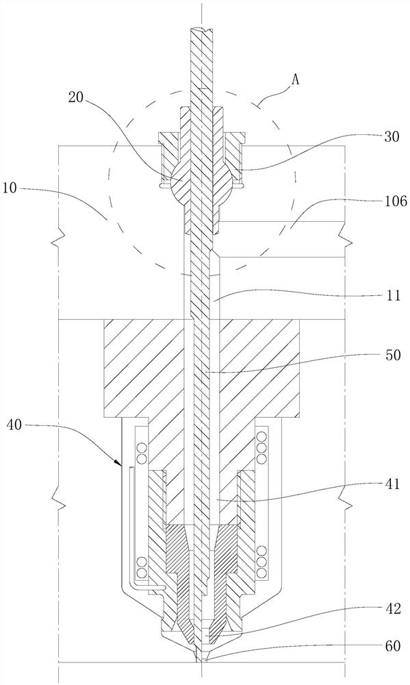
The invention relates to a valve needle guide structure, a valve needle guide positioning method and an injection mold. The valve needle guide structure comprises a splitter plate, a guide piece and a cover body, a through hole penetrating up and down is formed in the splitter plate, and a first annular groove is formed in the top of the through hole; the guide piece is of a rotary body structure with a center guide hole, the peripheral face of the guide piece is a protruding arc face, and the guide piece is partially contained in the first annular groove and can be axially deflected and adjusted through cooperation of the arc face and the first annular groove; the cover body is provided with a clearance hole penetrating up and down, a second annular groove opposite to the first annular groove is formed in the bottom of the clearance hole, and the cover body covers the guide piece and is fixedly connected with the splitter plate so as to limit axial deflection of the guide piece. The guide part can be quickly fixed to the position where the center guide hole and the ejection hole of the hot runner nozzle are located on the same center axis, the structure is simple, the requirement for machining precision is low, and installation is convenient and quick.

Description

technical field [0001] The invention belongs to the technical field of molds, and in particular relates to a valve needle guide structure, a valve needle guide and positioning method, and an injection mold. Background technique [0002] The hot runner system is mainly used as a part of the injection mold. The function of the hot runner system is to keep the plastic in a molten state during the injection molding process, and at the same time guide the molten plastic to different mold cavities to avoid the waste of nozzle materials. It is beneficial to reduce injection pressure, shorten injection cycle and improve product quality. [0003] The existing hot runner system structure such as figure 1 As shown, it mainly includes a guide body 102, a fixed sleeve 103 and a hot runner nozzle 104. The guide body 102 is fixedly installed on the top surface of the distribution plate 101 through the fixed sleeve 103, the hot runner nozzle 104 is arranged on the bottom surface of the dis...

Claims


Application Information

Patent Timeline
Patent Type & Authority Applications(China)
IPC IPC(8): B29C45/27B29C45/28
CPCB29C45/27B29C45/28
Inventor 陈兆鸣
Owner EVERFINEST PRECISION MACHINERY SHENZHEN
Why Eureka
Try Eureka