Bending reinforced concrete simply supported beam

A technology of reinforced concrete and simply supported beams, applied in the processing of building materials, structural elements, building components, etc., can solve the problems of difficult reinforcement layout, cumbersome process, brittle failure of super-reinforced beams, etc., achieve effective reinforcement and improve practicality Sexuality, the effect of reducing the demand for manpower

Pending Publication Date: 2022-03-08
黄勇
View PDF11 Cites 0 Cited by
  • Summary
  • Abstract
  • Description
  • Claims
  • Application Information

AI Technical Summary

Problems solved by technology

[0002] At present, in the structure of high-rise buildings, due to the complex load and stress form of the transfer floor girder, if ordinary reinforced concrete beams are used, a higher reinforcement ratio is generally required, which often leads to difficulties in the arrangement of reinforcement bars, and there may also be over-reinforced beams The hidden danger of brittle failure
[0003] Before pouring concrete, it is necessary to build simply supported beams with steel bars, which can make the entire concrete firm when it solidifies and improve the strength of the concrete. However, when building multiple steel bars, the process is very cumbersome and requires multiple Each steel bar is fixed one by one, which brings a lot of labor to people, and does not necessarily achieve a qualified fixing effect at the same time.

Method used


Image

  • Bending reinforced concrete simply supported beam
  • Bending reinforced concrete simply supported beam
  • Bending reinforced concrete simply supported beam

Examples


Embodiment Construction

[0028] The following will clearly and completely describe the technical solutions in the embodiments of the present invention with reference to the accompanying drawings in the embodiments of the present invention. Obviously, the described embodiments are only some, not all, embodiments of the present invention. Based on the embodiments of the present invention, all other embodiments obtained by persons of ordinary skill in the art without making creative efforts belong to the protection scope of the present invention.

[0029] see Figure 1 to Figure 6 , the present invention provides a technical solution:

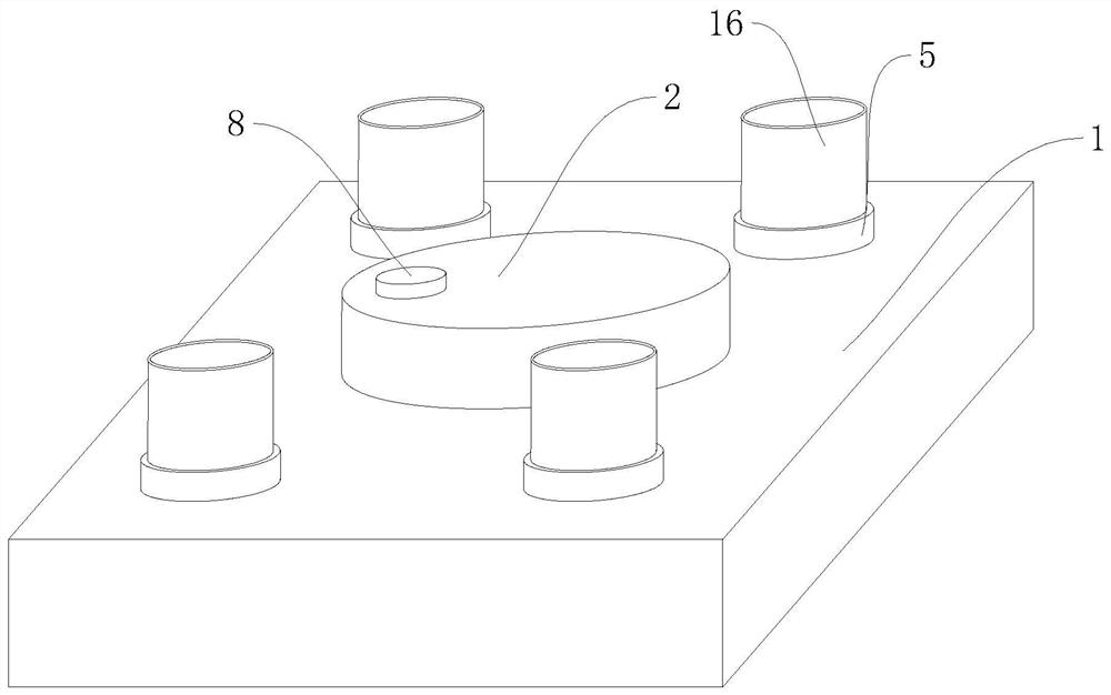
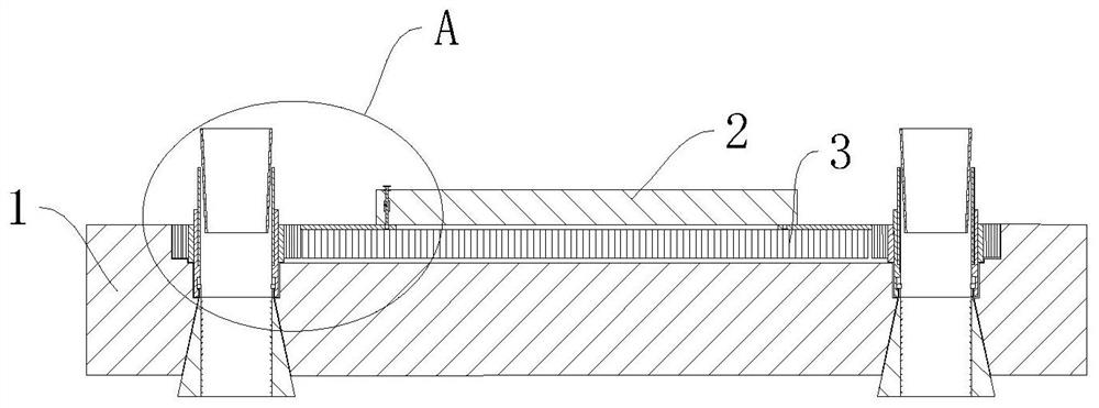
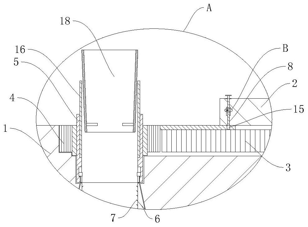
[0030] A simply supported flexural reinforced concrete beam, such as Figure 1 to Figure 3 As shown, it includes a base 1, the center of the upper end of the base 1 is rotatably connected with a turntable 2, the lower end of the turntable 2 is fixedly connected with a first gear 3, and the inside of the base 1 near the four corners are all Rotationally connected with a ...


PUM


Abstract

The invention relates to the technical field of buildings, in particular to a flexural reinforced concrete simply supported beam which comprises a base, a rotating disc is rotatably connected to the center of the upper end of the base, a first gear is fixedly connected to the lower end of the rotating disc, and second gears are rotatably connected to the positions, close to the four corners, of the interior of the base. A cylinder is fixedly connected to the interior of the second gear, extrusion blocks are rotatably connected to the left side and the right side of the lower end of the cylinder, the outer side of the first gear is in meshed connection with the outer side of the second gear, barbs are fixedly connected to the opposite sides of the extrusion blocks, and a moving rod is slidably connected to the position, close to the left side, of the interior of the rotating disc; the steel bar strut beam can be rapidly fixed, the requirement for manpower is reduced, compared with a steel wire and the like, the steel bar strut beam is more stable, meanwhile, in the upward pulling process, a certain tensile force is exerted on the steel bar, so that a certain prestress can be exerted on the steel bar, and concrete plays a more effective reinforcing role.

Description

technical field [0001] The invention relates to the technical field of buildings, in particular to a simply supported beam of reinforced concrete subjected to bending. Background technique [0002] At present, in the structure of high-rise buildings, due to the complex load and stress form of the transfer floor girder, if ordinary reinforced concrete beams are used, a higher reinforcement ratio is generally required, which often leads to difficulties in the arrangement of reinforcement bars, and there may also be over-reinforced beams The hidden danger of brittle failure. [0003] Before pouring concrete, it is necessary to build simply supported beams with steel bars, which can make the entire concrete firm when it solidifies and improve the strength of the concrete. However, when building multiple steel bars, the process is very cumbersome and requires multiple Each steel bar is fixed one by one, which brings a lot of labor to people, and can not necessarily achieve quali...

Claims


Application Information

Patent Timeline
Patent Type & Authority Applications(China)
IPC IPC(8): E04C5/16E04G21/12
CPCE04C5/162E04C5/168E04G21/122E04G21/12
Inventor 黄勇王贺
Owner 黄勇
Why Eureka
Try Eureka