Reverse support structure of steel bar truss

A steel truss, anti-support technology, applied in the direction of structural elements, building components, building structures, etc., can solve the problems of high cost of support equipment, difficult turnover of support frames, unfavorable recycling, etc., to achieve the effect of easy disassembly and turnover

Active Publication Date: 2022-03-18
THE FOURTH OF CHINA EIGHTH ENG BUREAU
View PDF10 Cites 0 Cited by
  • Summary
  • Abstract
  • Description
  • Claims
  • Application Information

AI Technical Summary

Problems solved by technology

[0004] The purpose of the present invention is to solve the following shortcomings in the prior art. Most of the existing reinforced truss floor decks are supported by scaffolding during construction, which makes the cost of supporting equipment relatively high, and when used in floors with different elevations, a variety of steel plates are required. Therefore, it is difficult to turn over the support frame, which is not conducive to recycling, and a steel truss anti-support structure is proposed

Method used


Image

  • Reverse support structure of steel bar truss
  • Reverse support structure of steel bar truss
  • Reverse support structure of steel bar truss

Examples


Embodiment Construction

[0028] The following will clearly and completely describe the technical solutions in the embodiments of the present invention with reference to the accompanying drawings in the embodiments of the present invention. Obviously, the described embodiments are only some, not all, embodiments of the present invention.

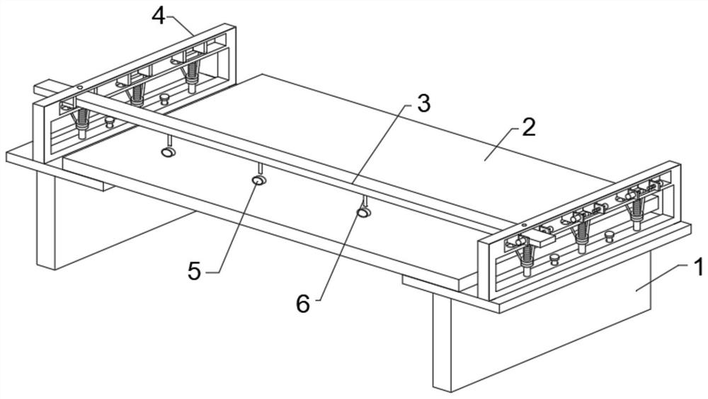
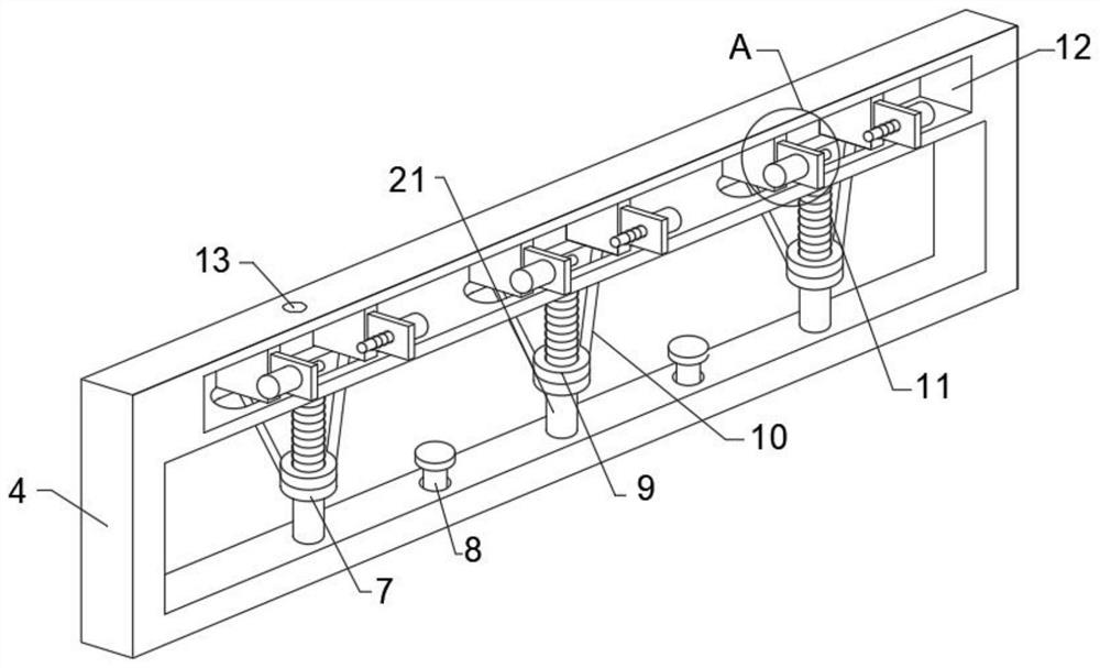
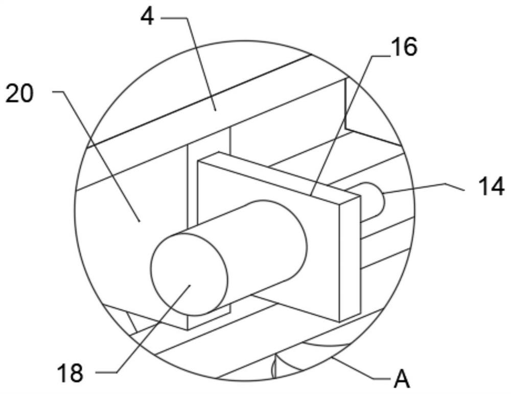
[0029] refer to Figure 1-4 , a steel truss anti-support structure, the steel truss anti-support structure includes:

[0030] The steel beam frame 1 and the steel truss floor deck 2 fixedly connected between the two steel beam frames 1, the steel beam frame 1 is arranged in a T shape, and the steel beam frame 1 is used to support and fix the steel bar truss floor deck 2 ;

[0031] The supporting part, the supporting part includes the installation frame 4, the horizontal plate 3, the prefabricated ring 5, and the steel cable 6, and the two installation frames 4 are respectively arranged on the steel beam frame 1, and the two installation frames 4 are respectively arr...


PUM


Abstract

The invention discloses a steel bar truss reverse supporting structure which comprises two steel beam frames, a steel bar truss floor bearing plate fixedly connected between the two steel beam frames, a supporting component, a steel bar truss supporting component and a steel bar truss supporting component, and the steel bar truss supporting component is used for supporting and fixing the steel bar truss floor bearing plate. The supporting component comprises mounting frames, transverse plates, prefabricated rings and steel cables, the two mounting frames are arranged on the steel beam frame, the multiple transverse plates are arranged between the two mounting frames in an equidistant array mode, the multiple prefabricated rings are fixedly connected to the steel bar truss floor support plate, the steel cables are arranged on the transverse plates in an equidistant array mode, and the steel cables are fixedly connected to the steel bar truss floor support plate. When the lantern ring moves downwards, the inclined rods are pulled, the two inclined rods drive the clamping blocks to move in the middle, the transverse plate is clamped and fixed, at the moment, the transverse plate and the mounting frame are fixedly connected through external screws through the fixing holes, the effect of rapidly fixing the transverse plate is achieved, and meanwhile disassembly and turnover are convenient.

Description

technical field [0001] The invention relates to the technical field of building construction equipment, in particular to a reinforced truss anti-support structure. Background technique [0002] The steel truss floor deck is a kind of unsupported pressure-type composite floor deck; the steel truss is finalized and processed in the background processing field, and the on-site construction needs to first fix the pressure plate on the steel beam with bolts, and then place the steel truss Binding is carried out, concrete is poured after acceptance, and mechanized production is realized, which is conducive to the uniform arrangement of steel bars and the uniform thickness of the concrete cover, which improves the construction quality of the floor. Improve construction progress, increase construction safety guarantee, and realize civilized construction. [0003] Most of the existing reinforced truss floor decks are supported by scaffolding during construction, which makes the supp...

Claims


Application Information

Patent Timeline
Patent Type & Authority Applications(China)
IPC IPC(8): E04B5/17E04C5/16E04C5/18
CPCE04B5/17E04C5/168E04C5/18Y02E10/50
Inventor 岳一森姜明明赵光远齐闻陈浩肖仕浪
Owner THE FOURTH OF CHINA EIGHTH ENG BUREAU
Why Eureka
Try Eureka