
Camera bearing device and control method thereof

A bearing device and camera technology, applied in the direction of supporting machines, image communication, mechanical equipment, etc., can solve the problems of limited motor speed and difficult processing, etc., and achieve the effect of simple transmission connection mode and stable transmission connection mode

Active Publication Date: 2022-03-08
北京注色影视科技有限公司
View PDF6 Cites 0 Cited by
  • Summary
  • Abstract
  • Description
  • Claims
  • Application Information

AI Technical Summary

Problems solved by technology

In actual production and processing, the longer the screw rod, the more difficult the processing, and the motor speed is also limited. Breaking through the lifting height and lifting speed, it is unrealistic to simply use a higher production process and a higher speed drive motor. A better structural design

Method used


Image

  • Camera bearing device and control method thereof
  • Camera bearing device and control method thereof
  • Camera bearing device and control method thereof

Examples


Embodiment Construction

[0040] In order to make the purpose, technical solutions and advantages of the embodiments of the present invention clearer, the technical solutions in the embodiments of the present invention will be clearly and completely described below in conjunction with the accompanying drawings. Apparently, the described embodiments are some, not all, embodiments of the present invention.

[0041] Therefore, the following detailed description of the embodiments of the present invention is not intended to limit the scope of the claimed invention, but merely represents some embodiments of the present invention. Based on the embodiments of the present invention, all other embodiments obtained by persons of ordinary skill in the art without creative efforts fall within the protection scope of the present invention.

[0042] It should be noted that, in the case of no conflict, the embodiments of the present invention and the features and technical solutions in the embodiments can be combined w...


PUM


Abstract

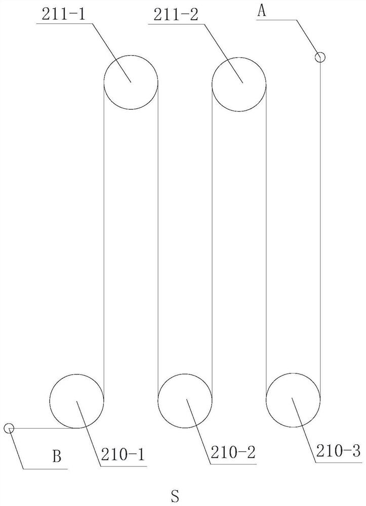
The invention relates to a camera bearing device and a control method thereof. The camera bearing device comprises a lifting arm assembly; the holder is mounted at the lifting end of the lifting arm assembly and used for supporting a camera; the lifting arm assembly comprises a fixed arm and a multi-stage lifting arm, the fixed arm is internally provided with a hollow lifting channel, the fixed arm is fixedly arranged, and the lifting arm and the fixed arm as well as the lifting arms at all stages are sleeved in a lifting sliding manner; the lifting arm assembly further comprises a lifting steel cable mechanism and a linkage steel cable mechanism, the fixed arm and the lifting arms are in transmission connection through the lifting steel cable mechanism, the multiple stages of lifting arms are in transmission connection through the lifting steel cable mechanism, and the lifting arms are driven by the lifting steel cable mechanism to ascend and descend. The fixed arm and the lifting arms as well as the multiple stages of lifting arms are in transmission connection through linkage steel cable mechanisms, and synchronous lifting of the lifting arms at all stages is achieved through the linkage steel cable mechanisms. The camera bearing device can perform more-stage transmission and larger-range lifting, and is more stable and reliable.

Description

technical field [0001] The present invention relates to the technical field of video equipment, in particular to a camera carrying device and a control method thereof. Background technique [0002] In the radio and television industry, there is a need for shooting, which is to achieve a stable rise or fall of the camera in the vertical height, to ensure the process of rising or falling, and the whole picture can be used as the broadcast picture, and no shaking, shaking and other phenomena that affect the shooting effect are allowed. . This just needs a kind of camera carrying device to realize this function. [0003] In the prior art, usually the mechanical structure of the lifting part is mainly realized by a screw rod. Generally, it will be made into a multi-stage screw. In such a structure, the lifting height depends on the odd number of the screw and the length of the screw. The lifting speed depends on the motor speed and the pitch of the screw. In actual production ...

Claims


Application Information

Patent Timeline
Patent Type & Authority Applications(China)
IPC IPC(8): F16M11/04F16M11/18H04N5/225H04N5/232
CPCF16M11/046F16M11/18H04N23/54H04N23/685
Inventor 郑彦维
Owner 北京注色影视科技有限公司
Learn More