
Material quality inspection method and device and supplied material quality visual inspection system

A quality inspection and material technology, applied in the field of incoming material inspection, can solve problems such as loss, complex server configuration, and upgrade, and achieve the effect of improving efficiency and accuracy

Pending Publication Date: 2022-03-08
INSPUR SUZHOU INTELLIGENT TECH CO LTD
View PDF0 Cites 3 Cited by
  • Summary
  • Abstract
  • Description
  • Claims
  • Application Information

AI Technical Summary

Problems solved by technology

IQC is the checkpoint for controlling the quality of enterprise products before production. If unqualified materials are put into the manufacturing process, it will lead to unqualified manufacturing processes or final products, causing huge losses, especially with the development of big data and cloud computing. With the rapid development of artificial intelligence and other fields, the configuration of servers in various application scenarios is becoming more and more complex, so the complexity of product development is also increasing accordingly. While product performance is improving, the requirements for quality inspection of components or electronic components and other materials also increased accordingly
[0003] In the related technology, the IQC incoming material inspection usually involves the inspector searching for the corresponding specification in the relevant system according to the supplier's material number of the material, and comparing the parameters in the specification with the material parameters. IQC factory inspection takes a long time, and the operation process is complicated and cumbersome, and the inspection efficiency and accuracy are low

Method used


Image

  • Material quality inspection method and device and supplied material quality visual inspection system
  • Material quality inspection method and device and supplied material quality visual inspection system
  • Material quality inspection method and device and supplied material quality visual inspection system

Examples


Embodiment Construction

[0043] In order to make the purpose, technical solution and advantages of the present application clearer, the present application will be further described in detail below in conjunction with the accompanying drawings and embodiments. It should be understood that the specific embodiments described here are only used to explain the present application, and are not intended to limit the present application.

[0044] In order to facilitate the understanding of the solution of the present application, the application environment applicable to the embodiment of the present application is firstly introduced.

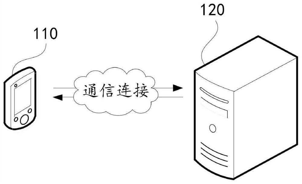
[0045] figure 1 It is a schematic diagram of the application scene of the material quality inspection method in an embodiment, such as figure 1As shown, the application environment includes a terminal device 110 and a server 120 establishing a communication connection through a network. The terminal device 110 can be used to scan the material to be inspected to obtain the i...


PUM


Abstract

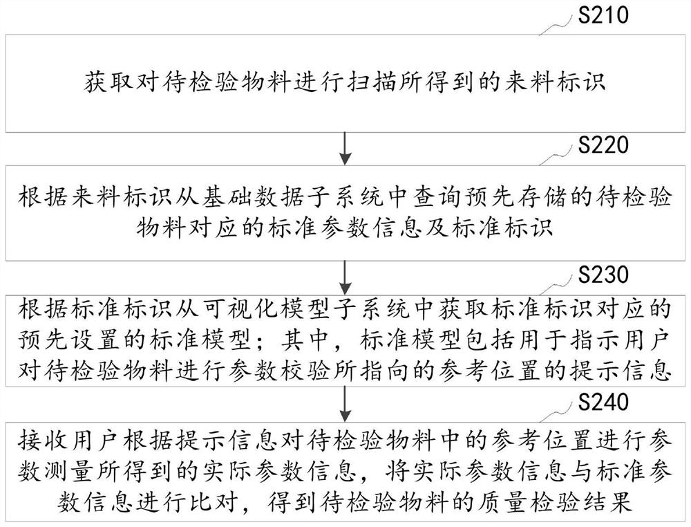
The invention relates to a material quality inspection method and device and an incoming material quality visual inspection system, and relates to the field of incoming material inspection.The method comprises the steps that an incoming material identifier obtained by scanning a to-be-inspected material is obtained, and standard parameter information and a standard identifier corresponding to the to-be-inspected material are inquired from a basic data subsystem according to the incoming material identifier; and according to the standard identifier, obtaining a standard model corresponding to the standard identifier from a visual model subsystem, so that a user performs parameter measurement on the to-be-inspected material according to prompt information of a reference position pointed by performing parameter verification on the to-be-inspected material in the standard model, and receiving actual parameter information obtained by performing parameter measurement on the reference position in the to-be-inspected material by a user, and comparing the standard parameter information with the actual parameter information to obtain a quality inspection result of the to-be-inspected material. According to the technical scheme, the visual inspection of the quality of the supplied materials can be realized, and the efficiency and the accuracy of the quality inspection of the supplied materials are improved.

Description

technical field [0001] The application relates to the field of incoming material inspection, in particular to a material quality inspection method and device, a visual inspection system for incoming material quality, and also relates to a computer device and a computer-readable storage medium. Background technique [0002] IQC (Incoming Quality Control) refers to the quality confirmation and inspection of purchased raw materials, components or products, that is, the products are inspected by sampling when suppliers deliver raw materials or components, and finally Make a judgment whether the batch of products is accepted or returned. IQC is the checkpoint for controlling the quality of enterprise products before production. If unqualified materials are put into the manufacturing process, it will lead to unqualified manufacturing processes or final products, causing huge losses, especially with the development of big data and cloud computing. With the rapid development of art...

Claims


Application Information

Patent Timeline
Patent Type & Authority Applications(China)
IPC IPC(8): G06Q10/06
CPCG06Q10/06395
Inventor 姜美瑶
Owner INSPUR SUZHOU INTELLIGENT TECH CO LTD
Learn More