
Transformer bushing capable of rapidly dissipating heat

A transformer bushing and bushing technology, which is applied in transformer/inductor cooling, transformer/inductor coil/winding/connection, etc., can solve the problems of high production cost and poor heat dissipation performance of conductive rods, and achieve convenient production and excellent structure Simple and effective in improving heat dissipation conditions

Pending Publication Date: 2022-03-08
江苏金诺电气科技有限公司
View PDF1 Cites 0 Cited by
  • Summary
  • Abstract
  • Description
  • Claims
  • Application Information

AI Technical Summary

Problems solved by technology

[0006] The purpose of the present invention is to overcome the shortcomings of existing transformer bushings, such as poor heat dissipation performance of conductive rods and high production costs, and provide a transformer bushing that can quickly dissipate heat. By adopting the technical solution of the present invention, the oil in the bushing and the temperature in the transformer are increased. The oil exchange channel uses the transformer oil to quickly take away the heat generated by the conductive rod, which improves the heat dissipation conditions of the conductive rod and improves the heat dissipation efficiency of the conductive rod, thereby helping to improve the service life and performance of the transformer bushing; and, further Reduce the material of the conductive rod and the use of lock nuts, and reduce the production cost of the transformer bushing

Method used


Image

  • Transformer bushing capable of rapidly dissipating heat
  • Transformer bushing capable of rapidly dissipating heat
  • Transformer bushing capable of rapidly dissipating heat

Examples


Embodiment

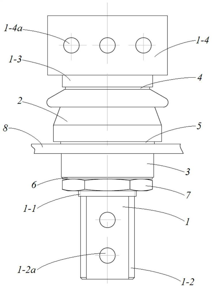
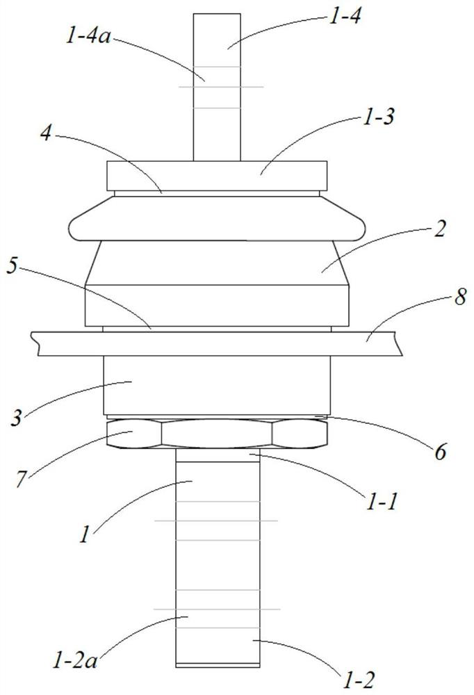
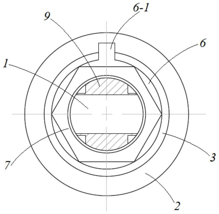
[0034] combine Figure 1 to Figure 6 As shown, a transformer bushing that can quickly dissipate heat in this embodiment includes a conductive rod 1 and an insulating sealing sleeve assembly sleeved on the outside of the conductive rod 1. The conductive rod 1 is used to lead the high and low voltage leads in the transformer to the Outside the oil tank, the insulating sealing sleeve assembly is used to realize the insulation and sealing between the conductive rod 1 and the oil tank wall 8 . Different from the existing transformer bushings, the conductive rod 1 has a cross-sectional shape capable of forming an oil cavity 9 on both sides of the insulating sealing bushing assembly, that is, between the conductive rod 1 and the central through hole of the insulating sealing bushing assembly. An oil cavity 9 is formed between them, and the oil cavity 9 communicates with the cavity inside the oil tank wall 8 of the transformer, so that the oil in the transformer oil tank can enter the...


PUM


Abstract

The invention discloses a transformer bushing capable of rapidly dissipating heat, and belongs to the field of transformer bushings. The transformer bushing capable of rapidly dissipating heat comprises a conducting rod and an insulation sealing bushing assembly arranged on the outer side of the conducting rod in a sleeving mode, the conducting rod is provided with a cross section shape capable of forming an oil cavity on the two sides with the insulation sealing bushing assembly, the oil cavity is communicated with a cavity on the inner side of an oil tank wall of a transformer, and an oil guide hole is further formed in the conducting rod. One end of the conducting rod is provided with a limiting structure, the other end of the conducting rod locks the insulation sealing sleeve assembly through a locking nut, a gasket is arranged between the locking nut and the insulation sealing sleeve assembly, and the gasket is provided with a rotation stopping gasket hole and a bending anti-loosening part. An exchange channel for oil in the sleeve and oil in the transformer is added, heat generated by the conducting rod is rapidly taken away through the transformer oil, and the heat dissipation efficiency of the conducting rod is improved; and moreover, the material of the conducting rod and the use of the locking nut are further reduced, and the manufacturing cost of the transformer bushing is reduced.

Description

technical field [0001] The invention relates to a transformer bushing, in particular to a transformer bushing capable of rapidly dissipating heat. Background technique [0002] With the rapid development of my country's electric power industry, the use of transformers has increased sharply, and the performance requirements of transformers are also higher. During the working process of the transformer, the transformer bushing is one of the key components that affect the performance of the transformer's power transmission and transformation. The main function of the transformer bushing is to lead the high and low voltage leads inside the transformer to the outside of the oil tank. It not only serves as insulation for the leads to the ground, but also serves as a fixed lead. During the operation of the transformer, the load current passes through it for a long time. When a short circuit occurs outside the transformer through the short circuit current. [0003] The existing tr...

Claims


Application Information

Patent Timeline
Patent Type & Authority Applications(China)
IPC IPC(8): H01F27/29H01F27/32H01F27/12
CPCH01F27/29H01F27/32H01F27/12
Inventor 戴波项大卫
Owner 江苏金诺电气科技有限公司
Learn More