Eureka AIR delivers breakthrough ideas for toughest innovation challenges, trusted by R&D personnel around the world.

Anti-falling structure for smart phone

A smart phone, anti-fall technology, applied in the direction of telephone structure, telephone communication, electrical components, etc., can solve the problems of reducing the service life of smart phones, high cost of screen maintenance, and less protection of physical buttons, so as to enhance the overall strength, The effect of reducing weight and maintaining aesthetics

Inactive Publication Date: 2022-03-08
安徽酷米智能科技股份有限公司
View PDF0 Cites 0 Cited by
  • Summary
  • Abstract
  • Description
  • Claims
  • Application Information

AI Technical Summary

Problems solved by technology

In order to improve the performance of image visual effect, operability, portability and function expansion, the current smart phones usually adopt large screen and light and thin as the mainstream design, and the problems brought by it are also obvious, that is, the existing smart phones The anti-drop performance is very poor, especially the screen part which is relatively fragile and has a large exposed area is easily broken
[0003] Generally, when falling from a high place or falling to the ground by gravity, the electronic components or motherboard inside will be damaged. When falling from a low height, the screen is also prone to cracking (the cost of repairing the screen of a smartphone is often high), which seriously reduces the The service life of the smart phone, and the physical button on the phone as the most fragile part of the smart phone has also brought a lot of trouble to the user. After the physical button is pressed or broken, the user needs to spend a lot of money. cost, and in the prior art, most of the protection for physical buttons is less

Method used


Image

  • Anti-falling structure for smart phone
  • Anti-falling structure for smart phone
  • Anti-falling structure for smart phone

Examples


Embodiment

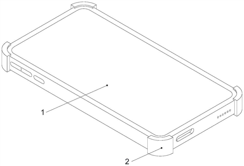
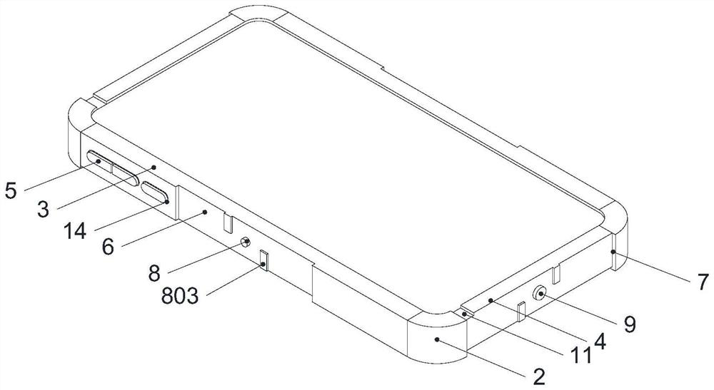
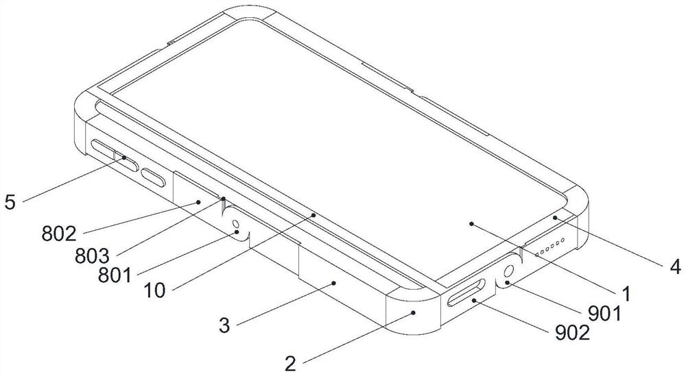
[0026] Example: such as Figure 1-5 As shown, the present invention is an anti-drop structure for smart phones, including a mobile phone main body 1, the four corners of the mobile phone main body 1 are respectively engaged and connected with ferrules 2, and the two ferrule sleeves 2 on the same side of the mobile phone main body 1 are fixed to each other. The first connecting piece 3 is connected, and the second connecting piece 4 is fixedly connected between the two ferrules 2 at the same end of the mobile phone main body 1. The first connecting piece 3 on one side of the mobile phone main body 1 is provided with three key sets 5, two second First grooves 6 are provided on the outside of one connecting piece 3 , and second grooves 7 are provided on the outside of the two second connecting pieces 4 .

[0027] The first rotating shaft 8 is arranged inside the first groove 6, and the first rotating disc 801 is arranged on the outside of the first rotating shaft 8, and the outer...


PUM


Abstract

The anti-falling structure comprises a mobile phone body, clamping sleeves are connected to the outer portions of the four corners of the mobile phone body in a clamped mode respectively, a first connecting piece is fixedly connected between the two clamping sleeves on the same side of the mobile phone body, and a second connecting piece is fixedly connected between the two clamping sleeves at the same end of the mobile phone body. Three key sleeves are arranged on first connecting pieces on one side of the mobile phone body, first grooves are formed in the outer sides of the two first connecting pieces, and second grooves are formed in the outer sides of the two second connecting pieces. According to the anti-falling structure for the smart phone, the contact spring, the rubber pad and the buffer layer are arranged, the buffer layer can buffer most of extrusion to the physical key, the contact spring can buffer external impact force borne by the physical key, and the anti-falling structure is simple in overall structure and convenient to use. The safety of the physical keys of the mobile phone is improved, the thickness of the mobile phone is not additionally increased, and the attractiveness and the integrity of the mobile phone are ensured.

Description

technical field [0001] The invention relates to the technical field of an anti-drop structure for smart phones, in particular to an anti-drop structure for smart phones. Background technique [0002] With the rapid development of science and technology, the functions of smart phones are becoming more and more powerful. It is not only used as a mobile communication device, but also integrated into people's daily life from many aspects. It can be described as a daily necessity for people today. In order to improve the performance of image visual effect, operability, portability and function expansion, the current smart phones usually adopt large screen and light and thin as the mainstream design, and the problems brought by it are also obvious, that is, the existing smart phones The anti-drop performance is very poor, especially the screen part which is relatively fragile and has a large exposed area is easily broken. [0003] Generally, when falling from a high place or fall...

Claims


Application Information

Patent Timeline
Patent Type & Authority Applications(China)
IPC IPC(8): H04M1/18
CPCH04M1/185
Inventor 陈晓敏钱佩金红桃
Owner 安徽酷米智能科技股份有限公司
Why Eureka
Eureka Blog
Learn More