Data sending method, data receiving processing method and related equipment

A data sending method and technology of sending equipment, applied in the field of communication, can solve problems such as low resource utilization rate, and achieve the effect of improving utilization rate

Pending Publication Date: 2022-03-08
VIVO MOBILE COMM CO LTD
0 Cites 2 Cited by

AI-Extracted Technical Summary

Problems solved by technology

[0005] The embodiment of the present application provides a data sending method, a data receiving a...

Method used

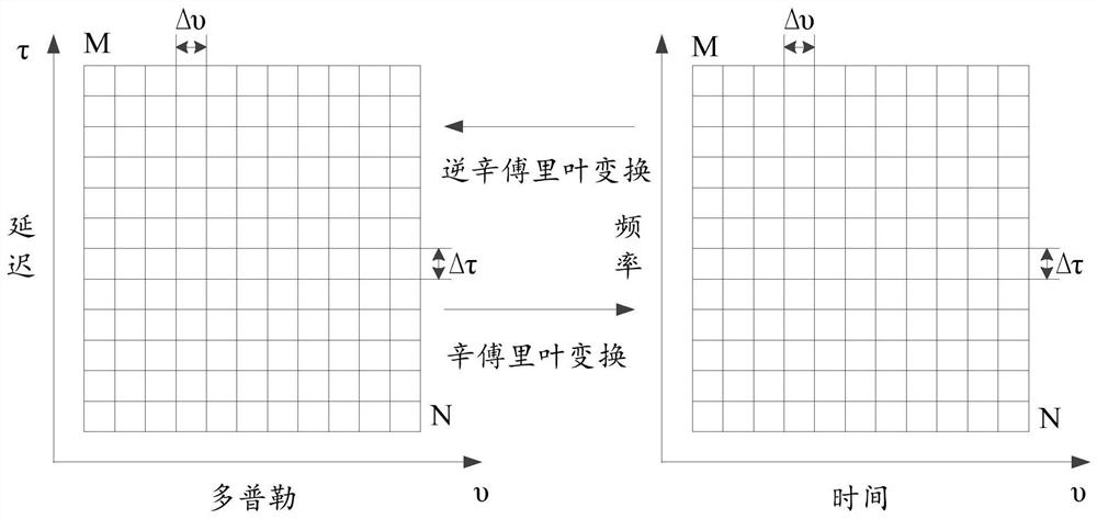
Embodiments of the present application transform the delayed Doppler domain data set on the delayed Doppler resource block into a time-frequency domain data set; according to preset resource mapping rules, the time-frequency domain data set is mapped to On a time-frequency resource block; sending the time-frequency domain data set on the time-frequency resource block; wherein, the resource mapping rule includes sparse mapping. In this way, a large amount of resource occupation caused by increasing M and N can be avoided, so the embodiment of the present application improves resource utilization and is relatively low.
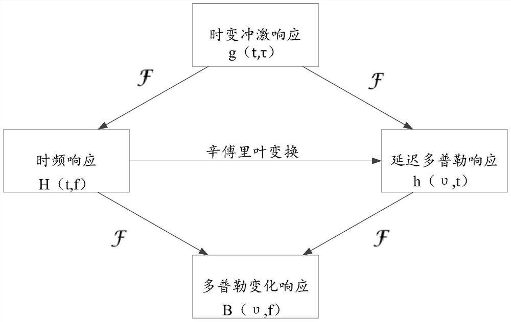
Thus, the OTFS technology transforms the time-varying multipath channel into a time-invariant two-dimensional delayed Doppler domain channel (in a certain duration), thereby directly reflecting the wireless link due to the The channel delay Doppler response characteristics caused by the geometric characteristics of the relative positions of the reflectors. The advantage of this is that OTFS eliminates the difficulty of traditional time-frequency domain analysis to track time-varying fading characteristics, and instead extracts all diversity characteristics of time-frequency domain channels through delay-Doppler domain analysis. In the actual system, the delay path and Doppler frequency shift of the channel are much smaller than the time domain and frequency domain response of the channel, so the channel represented by the delay Doppler domain is relatively simple. Therefore, using OTFS technology to analyze in the delayed Doppler domain can make the encapsulation of reference signals more compact and flexible, and is especially beneficial to support large-scale multiple-input multiple-output (MIMO) systems. antenna array.
[0076] The OTFS system resolves the reflector in the physical channel through the delayed Doppler image, and uses a receiving equalizer to coherently combine the energy from different reflection paths, which actually provides a static channel response without fading. Utilizing the above-mentioned static channel characteristics, the OTFS system does not need to introduce closed-loop channel adaptation to deal with fast-changing channels like the OFDM system, thus improving system robustness and reducing the complexity of system design.
[0078] Another superiority of OTFS is reflected on the extreme Doppler channel. Through the analysis of delayed Doppler images under appropriate signal processing parameters, the Doppler characteristics of the channel will be fully presented, which is beneficial to signal analysis and processing in Doppler-sensitive scenarios (such as high-speed movement and millimeter waves).
[0...

Abstract

The invention discloses a data sending method, a data receiving and processing method and related equipment. The method comprises the following steps: converting a delay Doppler domain data set on a delay Doppler resource block into a time-frequency domain data set; mapping the time-frequency domain data set to a time-frequency resource block according to a preset resource mapping rule; the time-frequency domain data set on the time-frequency resource block is sent; wherein the resource mapping rule comprises sparse mapping. The embodiment of the invention improves the utilization rate of resources.

Application Domain

Network traffic/resource managementMulti-frequency code systems +1

Technology Topic

EngineeringReal-time computing +5

Image

  • Data sending method, data receiving processing method and related equipment
  • Data sending method, data receiving processing method and related equipment
  • Data sending method, data receiving processing method and related equipment

Examples

  • Experimental program(2)

Example Embodiment

[0129] EXAMPLE 1: In the multi-user multiplexed scene, the interleaving placement of different user data has reached the function of increasing delay and Doppler resolution, enhancing channel estimation accuracy. Image 6 Time frequency domain resolution is:
[0130]
[0131] In the present application, the delay and Doppler resolution of the channel estimation can be improved by sparse mapping the transformed delay Doppler field QAM symbols on the physical time frequency domain resources. It is assumed that a dimension of the user data is sparse map, the symbol interval and the subcarrier spacers are AΔT and BΔF, respectively, and the mapping data is distributed in a rectangular resource block. Such as Figure 9 The sparse mapping occupies the scope shown in the dashed box.
[0132] If only single user data is available, the physical time-frequency resource block size needs to be assigned to [L + (L-1) (B-1)] * [K + (K-1) (A-1)], compared to the original The size of the data is due to the additional resource overhead:
[0133]
[0134] In order to further avoid waste of resources, multiple users can pass through the interleaving method, sparse mapped on a physical time-frequency resource block. Where A and B are positive integers.
[0135] In order to avoid waste of resources, multiple users can be interleaved, sparse mapped on a physical time-frequency resource block. Specific Figure 8 Indicated. exist Figure 8 In total, there is a total of P users and represent different fills. Each user's data block is a QAM symbol set on the delay Doppler area of ​​L × K. The logical time-consted time-only time-constricted time-frequency time-consuming logic is p * l * k. The data of the P user's data will be abandoned to the physical resources of the time-domain through the method of the present application, and the number of occupies is still p * l * k. Therefore, in the case of multi-user, the way of interleaving mapping and sparse mapping proposed in this application will not produce additional overhead.
[0136] It will be appreciated that the data transmission method of this application can be applied to uplink or is also applied to down.
[0137] Alternatively, in some embodiments, each UE resource is scheduled by the base station based on the optimized interleaving method. Each UE receives only data dispatched to its own resources, and according to the characteristics of the resource block, ie (M, N, ΔF) performs OTFS transform, to delay Doppler fields, channel measurement, channel estimation and decoding .
[0138] In other embodiments, when used for uplink, it is also necessary to scheder each UE resource by the base station to form an optimized interleaving method. Each UE is only scheduled to its own resource, and the OTFS transformation is transmitted according to the characteristics of the resource block, and the otM symbol is transmitted to the time frequency domain. After receiving the messages sent by the UE, the base station is separately decoded according to the known resource scheduling case.
[0139] The transmission of (M, N, ΔF) can be determined by the following manner:
[0140] The resource position is directly indicated by the base station to the UE;
[0141] Several different interleaving frame structural modes are specified, indicating the intra resource index to the UE;
[0142]Several different interleaving frame structural modes are specified by the protocol, and the UE selects the resource location according to your own ID.

Example Embodiment

[0143] Embodiment 2: In the multi-user multiplexed scene, the interleaving placement of different user data has reached the function of increasing delay and Doppler resolution, enhancing channel estimation accuracy.
[0144] In the present application embodiment, the delay resolution of the channel estimation can be improved by sparse mapping the transformed delay Doppler field QAM symbols on the frequency domain. The Doppler resolution can only be implemented by selecting a larger N. Such as Figure 10 Demolved, compared to Image 6 In order to obtain 2 times Doppler resolution, the time domain resource number is required to be 2N, and the frequency domain resource becomes in the case of the total resource number. Therefore, in order to obtain 2 times the delay resolution, it is necessary to turn 4 times. Thus, the time domain and frequency domain resolution of the present embodiment are:
[0145]
[0146] See Figure 11 , Figure 11 It is a flowchart of a data receiving processing method provided by the embodiment of the present application, and the method is executed by the receiving device, such as Figure 11 As shown, including the following steps:
[0147] Step 1101, demodulate the received data, obtain the time domain dataset corresponding to the current processing time unit;
[0148] Step 1102, turn the time domain data set to the time frequency domain dataset;
[0149] Step 1103, according to the preset resource mapping rule, the third time-frequency domain data set corresponding to the receiving device is acquired from the time-frequency domain data;
[0150] Step 1104, turn the third time frequency domain data set to delay Doppler area data set;
[0151] The resource mapping rules include sparse mapping.
[0152] Alternatively, the sparse mapping includes any of the following:
[0153] Continuous mapping on the time domain, sparse mapping on the frequency domain;
[0154] Sparse mapping is performed on the time domain and frequency domain.
[0155] Alternatively, the resource mapping rules also include interleaving mapping for multiple time-frequency domain datasets, the interleaving mapping includes one of the following:
[0156] Only interleaved mapping on the frequency domain;
[0157] Interleaving mappings are performed on the time domain and frequency domain.
[0158] Alternatively, the plurality of time-frequency domain data columns belong to a plurality of receiving devices.
[0159] Alternatively, the mapping rule satisfies any of the following:
[0160] Rules 1, the time-frequency domain dataset for multiple receiving devices is only interleaved on the frequency domain, and continuous mapping is performed on the time domain, sparse mapping on the frequency domain;
[0161] Rule 2, the time-frequency domain dataset for multiple receiving devices is interleaved in the frequency domain and time domain, and sparse mapping is performed on the time domain and frequency domain.
[0162] Alternatively, the method further includes obtaining the step of the time domain dataset corresponding to the current processing time unit, the method further comprising:
[0163] The receiving transmitter transmits the first instruction information, the first instruction information to indicate the resource mapping rule.
[0164] Alternatively, the method further includes obtaining the step of the time domain dataset corresponding to the current processing time unit, the method further comprising:
[0165] Receive the second instruction information sent by the sending device;
[0166] Wherein, the second instruction information is used to indicate the time-frequency resource block where the time-frequency domain data set is located at the time-frequency resource grid in the current processing time unit, or corresponds to the current processing time unit. The time-frequency resource grid is divided into multiple time-frequency resource blocks according to the preset rules, the second instruction information is used to indicate the index value corresponding to the time-frequency resource block where the time-frequency domain dataset is located.
[0167] It should be noted that this embodiment is used as Figure 5 The implementation of the corresponding receiving apparatus corresponding to the embodiment, the specific embodiment can be found Figure 5 The illustrated embodiments are described, and the same beneficial effects are reached, and will not be described later in order to avoid repeated description.
[0168] It should be noted that the data transmission method provided by the present application embodiment may be a data transmitting device, or a control module for performing a data transmission method in the data transmission device. In the present application embodiment, the data transmitting apparatus is executed as an example, and the data transmitting apparatus provided in the present application embodiment will be described.
[0169] See Figure 12 , Figure 12 It is a structural diagram of a data transmitting apparatus provided by the embodiment of the present application, such as Figure 12 As shown, the data transmitting device 1200 includes:
[0170] The first transform module 1201 is configured to convert the delay Doppler field data set on the delay Doppler resource block into a time frequency domain data set;
[0171] The mapping module 1202 is configured to map the time-frequency domain data set to the time frequency resource block in accordance with a preset resource mapping rule;
[0172] The transmission module 1203 is configured to transmit the time-frequency domain dataset on the time-frequency resource block;
[0173] The resource mapping rules include sparse mapping.
[0174] Alternatively, the sparse mapping includes any of the following:
[0175] Continuous mapping on the time domain, sparse mapping on the frequency domain;
[0176] Sparse mapping is performed on the time domain and frequency domain.
[0177] Alternatively, the resource mapping rules also include interleaving mapping for multiple time-frequency domain datasets, the interleaving mapping includes one of the following:
[0178] Only interleaved mapping on the frequency domain;
[0179] Interleaving mappings are performed on the time domain and frequency domain.
[0180] Alternatively, the plurality of time-frequency domain data columns belong to a plurality of receiving devices.
[0181] Alternatively, the mapping rule satisfies any of the following:
[0182] Rules 1, the time-frequency domain dataset for multiple receiving devices is only interleaved on the frequency domain, and continuous mapping is performed on the time domain, sparse mapping on the frequency domain;
[0183] Rule 2, the time-frequency domain dataset for multiple receiving devices is interleaved in the frequency domain and time domain, and sparse mapping is performed on the time domain and frequency domain.
[0184] Alternatively, the mapping module 1202 is specifically used:
[0185] In the case where there is a first time frequency domain data set of at least two receiving devices in the target time unit, the sparse mapping and the interleave mapping are performed on the frequency domain for the first time frequency domain data set.
[0186] Continuous mapping is performed on the time domain for the second time-frequency domain data set within the target frequency unit;
[0187] Wherein, the target time unit is any time unit of the time frequency resource block, the target frequency unit being any of the frequency units of the time frequency block.
[0188] Alternatively, the mapping module 1202 is specifically used:
[0189] In the case where there is a first time frequency domain data set of at least two receiving devices in the target time unit, the sparse mapping and the interleave mapping are performed on the frequency domain for the first time frequency domain data set.
[0190] In the case where there is a second time-frequency domain data set of at least two receiving devices in the target frequency unit, the sparse mapping and the interleave mapping are performed on the time domain in the time domain;
[0191] Wherein, the target time unit is any time unit of the time frequency resource block, the target frequency unit being any of the frequency units of the time frequency block.
[0192] Alternatively, the transmitting module 1203 is further configured to transmit a first instruction information to the receiving device, the first instruction information to indicate the resource mapping rule.
[0193] Alternatively, the transmitting module 1203 is also used to transmit a second instruction information to the receiving device;
[0194] Wherein, the second instruction information is used to indicate the time-frequency resource block where the time-frequency domain data set is located at the time-frequency resource grid in the current processing time unit, or corresponds to the current processing time unit. The time-frequency resource grid is divided into multiple time-frequency resource blocks according to the preset rules, the second instruction information is used to indicate the index value corresponding to the time-frequency resource block where the time-frequency domain dataset is located.
[0195] The data transmitting apparatus 1200 provided by the embodiment of the present application can be implemented Figure 5 The various processes implemented in the method embodiment, in order to avoid repetition, will not be described here.
[0196] It should be noted that the data receiving processing method provided by the embodiment of the present application may be a data receiving processing device, or a control module for performing a data reception processing method in the data receiving processing apparatus. In the present application embodiment, the data receiving processing method is performed as an example, and the data receiving processing apparatus provided by the present application embodiment will be described.
[0197] See Figure 13 , Figure 13 It is a structural diagram of a data receiving processing apparatus provided by the embodiment of the present application, such as Figure 13 As shown, the data receiving processing device 1300 includes:
[0198] The demodulation module 1301 is used to demodulate the received data to obtain the time domain dataset corresponding to the current processing time unit;
[0199] The second transform module 1302 is configured to convert the time domain data set to a time frequency domain data set;
[0200] The module 1303 is acquired to obtain the third time-frequency domain data set corresponding to the receiving device in accordance with the preset resource mapping rules.
[0201] The third transform module 1304 is configured to convert the third time frequency domain data set to a delay Doppler area data set;
[0202] The resource mapping rules include sparse mapping.
[0203] Alternatively, the sparse mapping includes any of the following:
[0204]Continuous mapping on the time domain, sparse mapping on the frequency domain;
[0205] Sparse mapping is performed on the time domain and frequency domain.
[0206] Alternatively, the resource mapping rules also include interleaving mapping for multiple time-frequency domain datasets, the interleaving mapping includes one of the following:
[0207] Only interleaved mapping on the frequency domain;
[0208] Interleaving mappings are performed on the time domain and frequency domain.
[0209] Alternatively, the plurality of time-frequency domain data columns belong to a plurality of receiving devices.
[0210] Alternatively, the mapping rule satisfies any of the following:
[0211] Rules 1, the time-frequency domain dataset for multiple receiving devices is only interleaved on the frequency domain, and continuous mapping is performed on the time domain, sparse mapping on the frequency domain;
[0212] Rule 2, the time-frequency domain dataset for multiple receiving devices is interleaved in the frequency domain and time domain, and sparse mapping is performed on the time domain and frequency domain.
[0213] Alternatively, the method further includes obtaining the step of the time domain dataset corresponding to the current processing time unit, the method further comprising:
[0214] The receiving transmitter transmits the first instruction information, the first instruction information to indicate the resource mapping rule.
[0215] Alternatively, the method further includes obtaining the step of the time domain dataset corresponding to the current processing time unit, the method further comprising:
[0216] Receive the second instruction information sent by the sending device;
[0217] Wherein, the second instruction information is used to indicate the time-frequency resource block where the time-frequency domain data set is located at the time-frequency resource grid in the current processing time unit, or corresponds to the current processing time unit. The time-frequency resource grid is divided into multiple time-frequency resource blocks according to the preset rules, the second instruction information is used to indicate the index value corresponding to the time-frequency resource block where the time-frequency domain dataset is located.
[0218] The data receiving processing apparatus 1300 provided by the embodiment of the present application can be implemented. Figure 11 The various processes implemented in the method embodiment, in order to avoid repetition, will not be described here.
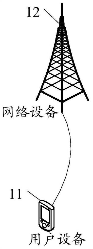
[0219] The data transmitting apparatus and data receiving processing apparatus in the present application embodiment may be a device, or a component, an integrated circuit, or a chip in the terminal. The device can be a mobile terminal or a non-mobile terminal. Exemplary, mobile terminals may include, but are not limited to, the type of terminal 11 listed above, non-mobile terminals can be servers, network attachs, NASs, Personal Computer, PCs, TVs ( TEEVISION, TV), teller or self-service, etc., the embodiments of the present application are not specified.
[0220] The data transmitting apparatus and data receiving processing apparatus in the present application embodiment may be a device having an operating system. The operating system can be an Android operating system, which can be an iOS operating system, and can also be other possible operating systems, and the present application is not specified.
[0221] The data transmitting apparatus and data receiving processing device provided herein can be implemented. Figure 5 to 11 Method Embodiment Implementing the various processes, and reaches the same technical effect, in order to avoid repetition, will not be described here.
[0222] Optional, such as Figure 14 As shown, the present application embodiment also provides a communication device 1400, including processor 1401, memory 1402, a program or instruction stored on memory 1402 and can operate on the processor 1401, for example, the communication device 1400 is When the device is transmitted, the program or instruction is executed by the processor 1401 to implement the various processes of the above-described data transmission method embodiment, and can achieve the same technical effect. When the communication device 1400 is a receiving device, the program or instruction is executed by the processor 1401 to implement the various processes of the above-described data reception processing method embodiment, and can achieve the same technical effect, in order to avoid repetition, here is not described herein.
[0223] Specifically, the present application embodiment provides a network side device. The network side device can be a receiving device or a transmission device. When the receiving device is a terminal, the transmitting device can be another terminal or network side device. When the receiving device is a network side device, the transmitting device is terminal. Such as Figure 15 As shown, the network side device 1500 includes antenna 1501, a radio frequency device 1502, a baseband device 1503. The antenna 1501 is connected to the radio frequency device 1502. In the uplink direction, the radio frequency device 1502 receives information through the antenna 1501, transmitting the received information to the baseband device 1503 for processing. In the downlink direction, the baseband device 1503 processes the information to be transmitted, and transmits the radio frequency device 1502, and the radio frequency device 1502 is sent to the received information after the antenna 1501 is transmitted.
[0224] The above-described frequency band processing device can be located in the baseband device 1503, and the method of the network side device executed in the above-described embodiment can be implemented in the baseband device 1503, the baseband device 1503 including processor 1504 and memory 1505.
[0225] The baseband device 1503 can, for example, comprise at least one base plate, and a plurality of chips are provided on the base plate, such as Figure 15 As shown, one of the chips is, for example, the processor 1504, connected to the memory 1505 to invoke the program in the memory 1505, and perform the network side device operation shown in the above method embodiment.
[0226] The baseband device 1503 may further include a network interface 1506 for interacting with the RF device 1502, which is, for example, a common common wireless interface (CPRI).
[0227] Specifically, the network side apparatus of the present application embodiment further includes an instruction or program stored on the memory 1505 and can run on the processor 1504, wherein the processor 1504 calls the memory when the network side device is a transmission device. Directive or program control execution in 1505 Figure 12 The method shown in each module is performed, and when the network side device is a receiving device, the processor 1504 calls the instruction or program execution in the memory 1505. Figure 13 The method shown in the respective modules is controlled and the same technical effect is achieved, and it is not repeated to avoid repeating.
[0228] Figure 16 A hardware structure of a terminal apparatus according to various embodiments of the present application is implemented.
[0229] The terminal device 1600 includes, but is not limited to, a radio frequency unit 1601, a network module 1602, an audio output unit 1603, an input unit 1604, a sensor 1605, a display unit 1606, a user input unit 1607, an interface unit 1608, a memory 1609, and a processor 1610 and other components. .
[0230] Those skilled in the art will appreciate that the terminal device 1600 can also include power supplies (such as batteries) that supply power (such as batteries) to each component, and the power supply can be connected to processor 1610 logic, thereby achieving management charging, discharging, and work through power management systems. Work management and other functions. Figure 16 The terminal device structure shown in the presentation does not constitute a defined of the terminal device, and the terminal device can include a component, or a combined part, or a different component arrangement, and will not be described again here.
[0231] It should be understood that in the present application embodiment, the input unit 1604 can include a graphics processor (GPU) 16041 and a microphone 16042, graphics processor 16041 pair by image capture devices in video capture mode or image capturing mode (eg The image data obtained by the camera) is processed. The display unit 1606 can include a display panel 16061, and a liquid crystal display, an organic light emitting diode or the like may be used to configure the display panel 16061. The user input unit 1607 includes a touch panel 16071 and other input devices 16072. Touch panel 16071, also known as touch screen. Touch panel 16071 can include a touch detecting device and a touch controller two portions. Other input devices 16072 may include, but are not limited to, physical keyboards, function keys (such as volume control buttons, switch buttons, etc.), trackball, mouse, and operating rod, and will not be described here again.
[0232] In the present application embodiment, the radio frequency unit 1601 receives the downlink data from the network side device to process the processor 1610; in addition, the uplink data is sent to the network device. Typically, the radio frequency unit 1601 includes, but is not limited to, at least one amplifier, transceiver, coupler, low noise amplifier, duplexer, and the like.
[0233] Memory 1609 can be used to store software programs or instructions and various data. Memory 109 can primarily include a memory program or instruction area and a storage data area, wherein the storage program or instruction zone can store the operating system, at least one of the applications or instructions (such as sound playback functions, image playback functions, etc.), and the like. Further, the memory 1609 can include a high speed random access memory, and may include a non-volatile memory, wherein the non-volatile memory can be a read-only memory (ROM), programmable read only memory (ProgramMable ROM) , PROM, erasable programmable read only memory (EraSable PROM, EPROM), electrically erasable programmable read only memory (EEPROM) or flash memory. For example, at least one disk storage device, flash device, or other non-volatile solid state memory device.
[0234] Processor 1610 can include one or more processing units; optional, processor 1610 can integrate application processors and modem processors, where the application processor mainly handles operating systems, user interfaces, and applications or instructions, etc. The modem processor mainly processes wireless communications, such as baseband processors. It will be appreciated that the above modulation processor may not be integrated into processor 1610.
[0235] Among them, when the transmitting device is terminal, the receiving device is another terminal or network side device,
[0236] Processor 1610 is used to: convert the delay Doppler field data set on the delay Doppler resource block into a time frequency domain data set; in accordance with a preset resource mapping rule, map the time-frequency domain data set to time frequency Resource block;
[0237] The radio frequency unit 1601 is for: transmitting the time frequency domain dataset on the time-frequency resource block;
[0238] The resource mapping rules include sparse mapping.
[0239] It should be understood that in the present embodiment, the processor 1610 and the radio frequency unit 1601 can be implemented. Figure 5 The various processes implemented in the method embodiment, in order to avoid repetition, will not be described here.
[0240] When the receiving device is terminal, the transmitting device is another terminal or network side device,
[0241] The RF unit 1601 is for:
[0242] Demodulate the received data to obtain the time domain dataset corresponding to the current processing time unit;
[0243] Move the time domain data set to a time frequency domain dataset;
[0244] According to the preset resource mapping rules, the third time-frequency domain dataset corresponding to the terminal device is obtained from the time-frequency domain data;
[0245] The third time frequency domain data set is converted to delay Doppler area data set;
[0246] The resource mapping rules include sparse mapping.
[0247] It should be understood that in the present embodiment, the processor 1610 and the radio frequency unit 1601 can be implemented. Figure 11 The various processes implemented in the method embodiment, in order to avoid repetition, will not be described here.
[0248] The present application embodiment also provides a readable storage medium that stores programs or instructions on the readable storage medium, the program or instructions perform each process of implementing the above data transmission method or data reception processing method embodiment when executed by the processor. And can achieve the same technical effect, in order to avoid repetition, will not be described here.
[0249] The processor is a processor in the electronic device described in the above embodiment. The readable storage medium includes a computer readable storage medium such as a computer read-only memory (ROM), random access memory (RAM), a disk, or an optical disk.
[0250] The present application embodiment provides a chip comprising a processor and a communication interface, the communication interface, and the processor coupled, the processor for running a network device program or instruction, implementing the above data reception processing method The various processes of the embodiments can achieve the same technical effect, in order to avoid repetition, will not be described here.
[0251] It will be understood that the chips mentioned in the present application may also be referred to as a system-level chip, a system chip, a chip system, or a chip system chip.

PUM

no PUM

Description & Claims & Application Information

We can also present the details of the Description, Claims and Application information to help users get a comprehensive understanding of the technical details of the patent, such as background art, summary of invention, brief description of drawings, description of embodiments, and other original content. On the other hand, users can also determine the specific scope of protection of the technology through the list of claims; as well as understand the changes in the life cycle of the technology with the presentation of the patent timeline. Login to view more.

Similar technology patents

Hardware product spraying device convenient to use

Owner:佛山市顺德区恒恩裕电器实业有限公司

Superdeep hydrodesulfurization catalyst and preparation method thereof

ActiveCN102049289AImprove pore structureincrease profit
Owner:CHINA PETROLEUM & CHEM CORP +1

Classification and recommendation of technical efficacy words

  • increase profit

Hydrodewaxing method for diesel fraction

ActiveCN102453531ARaise the reaction temperatureincrease profit
Owner:CHINA PETROLEUM & CHEM CORP +1

Full-period electric pressure cooker production control method

InactiveCN107713732ATargetedincrease profit
Owner:GUANGDONG HUILIPU ROAD & BRIDGE INFORMATION ENG

Mobile phone

InactiveCN102938796Aincrease profit
Owner:ZTE CORP

Window display method and system of application program and mobile terminal

ActiveCN102999253Aincrease profit
Owner:BEIJING QIYI CENTURY SCI & TECH CO LTD
Why Eureka
Try Eureka