
Atomization assembly, atomizer and aerosol generating device

A technology of atomization components and atomizers, which is applied in the field of atomization and can solve problems such as high heating efficiency, poor atomization effect, and large amount of atomization

Pending Publication Date: 2022-03-11
深圳市大迈发展有限公司
View PDF0 Cites 2 Cited by
  • Summary
  • Abstract
  • Description
  • Claims
  • Application Information

AI Technical Summary

Problems solved by technology

[0006] On the one hand, the above-mentioned atomizing component forms a physical distance between the atomizing surface and the liquid-absorbing surface, and the heating element indirectly contacts the atomizing medium in the liquid storage chamber through the guide part, so there is a long distance from the atomizing medium in the liquid storage chamber. Effective isolation of heat transfer can prevent high temperature from deteriorating the atomization medium in the liquid storage chamber, and the heat concentration of the entire atomization component makes the heating efficiency high; on the other hand, the atomization part and the oil guide part are connected, and the guide part passes through The liquid suction surface obtains the atomized medium, the oil guide area is large and the oil guides in all directions, which can effectively ensure the sufficient oil supply. The atomization effect is not good, and the amount of smoke is not enough

Method used

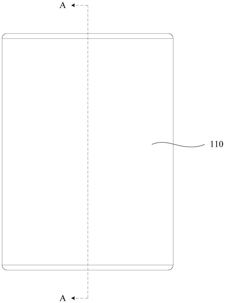

Image

  • Atomization assembly, atomizer and aerosol generating device
  • Atomization assembly, atomizer and aerosol generating device
  • Atomization assembly, atomizer and aerosol generating device

Examples


Embodiment Construction

[0041]In order to make the above-mentioned purpose, features and advantages of the present application more obvious and understandable, the specific implementation manners of the present application will be described in detail below in conjunction with the accompanying drawings. In the following description, numerous specific details are set forth in order to provide a thorough understanding of the application. However, the present application can be implemented in many other ways different from those described here, and those skilled in the art can make similar improvements without departing from the connotation of the present application, so the present application is not limited by the specific embodiments disclosed below. It should be noted that when a component is referred to as being “fixed on” or “set on” another component, it may be directly on the other component or there may also be an intervening component. When a component is said to be "connected" to another compo...


PUM


Abstract

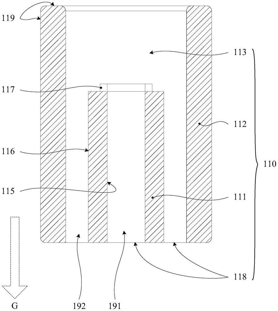
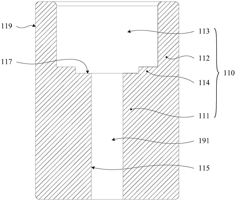
The invention relates to an atomization assembly, an atomizer and an aerosol generating device, a heating body is at least partially embedded in an atomization part, and the atomization part is fixed in a guide part; the guide part is in contact with the atomizing medium and transmits the atomizing medium to the atomizing part; the inner wall of the atomizing part forms a first atomizing surface and a first air channel, and the outer wall forms a second atomizing surface and a second air channel. On one hand, a physical interval is formed between the atomizing surface and the liquid absorbing surface, and the heating body indirectly contacts with the atomizing medium in the liquid storage cavity through the guide part, so that a long distance exists between the heating body and the atomizing medium in the liquid storage cavity, heat transfer is effectively isolated, and the atomizing medium in the liquid storage cavity can be prevented from deteriorating due to high temperature; due to heat concentration, the heating efficiency of the whole atomization assembly is high; on the other hand, the atomization part and the oil guide part are connected, the guide part obtains the atomization medium through the liquid suction face, the oil guide area is large, oil is guided in all directions, and sufficient oil supply can be effectively guaranteed.

Description

technical field [0001] The present application relates to the technical field of atomization, in particular to an atomization component, an atomizer and an aerosol generating device. Background technique [0002] Electronic atomization devices in the prior art are mainly composed of an atomizer and a power supply. The atomizer generally includes a liquid storage chamber and an atomization component. The liquid storage cavity is used to store the nebulizable medium, and the nebulizer component is used to heat and atomize the nebulizable medium to form an aerosol that can be consumed by smokers. ; The power supply is used to provide energy to the atomization components. [0003] In the traditional technology, the heating element on the atomizing core is usually installed on the oil-guiding surface of the oil-guiding element by printing, embedding, etc. or directly fixedly installed on the oil-guiding surface of the oil-guiding element. With such a heating element fixing meth...

Claims


Application Information

Patent Timeline
IPC IPC(8): A24F40/40A24F40/46A24F40/48A24F40/42A24F40/10
CPCA24F40/40A24F40/46A24F40/48A24F40/42A24F40/10
Inventor 张春华
Owner 深圳市大迈发展有限公司
Learn More