Pipe fitting weld joint polishing equipment

A technology of equipment and pipe fittings, which is applied in the field of pipe fitting weld grinding equipment, can solve the problems of low grinding precision, position changes of grinding parts, and simultaneous grinding of convex and concave parts that cannot be welded, so as to achieve high grinding precision and avoid positioning deviation , a wide range of grinding effect

Inactive Publication Date: 2022-03-11
HUZHOU TEACHERS COLLEGE +1
View PDF1 Cites 4 Cited by
  • Summary
  • Abstract
  • Description
  • Claims
  • Application Information

AI Technical Summary

Problems solved by technology

[0004] However, in this technical solution, only the raised portion of the arc-shaped weld can be ground during the grinding process, and it is impossible to simultaneously grind the raised portion and the concave portion of the weld, and the range of the polished surface is small. During the grinding process, the grinding parts are repeatedly turned over, and the operation is complicated. Because the arc-shaped weld seam is difficult to locate during the polishing process, the position of the grinding parts is prone to change during the continuous grinding process, and the grinding accuracy is low.

Method used


Image

  • Pipe fitting weld joint polishing equipment
  • Pipe fitting weld joint polishing equipment
  • Pipe fitting weld joint polishing equipment

Examples


Embodiment 1

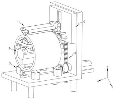
[0075] Such as Figure 1-2 Shown, a pipe fitting weld seam grinding equipment, including:

[0076] Grinding assembly 1, the grinding assembly 1 is distributed on the inner and outer ends of the grinding piece;

[0077] A detection unit 2, the detection unit 2 is arranged at the fixed end of the grinding assembly 1;

[0078] A fixing unit 4, the fixing unit 4 is arranged on the side of the detection unit 2;

[0079] After the grinding piece finds the position of the weld seam by the detection unit 2 during the rotation process, the position of the grinding piece is locked by the fixing unit 4, and a smooth grinding surface inside and outside is formed under the mode of grinding while the grinding assembly 1 is swinging.

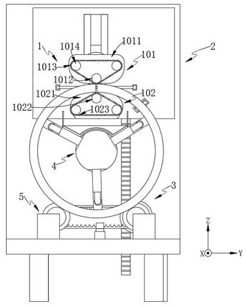
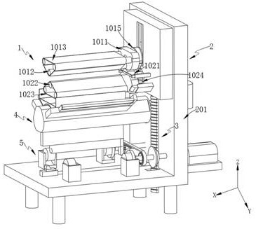
[0080] As an improvement, such as Figure 2-6 As shown, the grinding assembly 1 includes:

[0081] The first grinding roller 101;

[0082] The second grinding roller 102 is arranged at the lower part of the first grinding roller 101 .

[0083] Further, t...

Embodiment 2

[0139] Such as Figure 8 , Figure 11-12 As shown, the components that are the same as or corresponding to those in the first embodiment are marked with the corresponding reference numerals in the first embodiment. For the sake of simplicity, only the differences from the first embodiment will be described below. The difference between this embodiment two and embodiment one is:

[0140] By setting the air outlet 407 on the side of the inflation pipeline 402, after the grinding is finished, the driving motor 3011 drives the rack 2044 to move upward through the rotating roller 3012, and the rack 2044 drives the sleeve block 2042 to drive the lifting rod 2041 to move upward through the adjustment rod 2043. At this time, the first control valve 403 closes the inflation pipe 402, and at the same time the second control valve 404 opens the air outlet 407, so that the gas inside the gas storage tank 4061 and the limit assembly 501 flows back and is ejected at the air outlet 407, and...


PUM


Abstract

The invention provides pipe fitting weld joint polishing equipment which is characterized by comprising polishing assemblies distributed at the inner end and the outer end of a polishing piece; the detection unit is arranged at the fixed end of the polishing assembly; the fixing unit is arranged at the side part of the detection unit; after the position of the welding seam is found by the detection unit in the rotating process of the grinding piece, the position of the grinding piece is locked through the fixing unit; the arc length between the first prediction assembly and the second prediction assembly is set to be equal to the effective length of the rack, and it is ensured that when the reverse wedge-shaped plate is inserted into the welding seam, the first grinding roller and the second grinding roller just make the upper end face and the lower end face of a grinding piece make contact; therefore, the welding seam position of the grinding piece can be automatically detected.

Description

technical field [0001] The invention relates to the technical field of weld seam grinding of rolled pipes, in particular to a pipe fitting weld seam grinding equipment. Background technique [0002] After the metal iron sheet is wound into a tubular shape, it needs to be welded and formed. However, a rough weld will be formed at the weld. In order to smooth the weld, it is usually necessary to polish the weld so that the processed The surface of the metal pipe is smoother and more beautiful. [0003] Chinese patent CN 113458903 A discloses an arc-shaped weld seam polishing device on the surface of a steel container, which belongs to the field of weld seam polishing technology. A worm is meshed and connected between two symmetrical worm wheels, so that the worm can drive the left and right sides when rotating. The two worm gears rotate relative to each other synchronously, and adjust the position of the lower two rollers. By setting the screw and the screw sleeve with the th...

Claims


Application Information

Patent Timeline
Patent Type & Authority Applications(China)
IPC IPC(8): B24B21/00B24B21/18B24B41/06B24B41/02B24B49/00
CPCB24B21/008B24B21/18B24B41/067B24B41/02B24B49/00
Inventor 王培良金建忠许宇翔郝利峰蔡志端
Owner HUZHOU TEACHERS COLLEGE
Why Eureka
Try Eureka