
Pneumatic impeller

A technology of aerodynamic impellers and blades, applied in the directions of engine components, machines/engines, and blade supporting components, etc., can solve the problem that the generator cannot output power effectively, the natural gas pressure regulating station cannot realize self-power supply, and the generator cannot provide sufficient power, etc. question

Pending Publication Date: 2022-03-11
SHANGHAI UNIV OF ENG SCI
View PDF7 Cites 0 Cited by
  • Summary
  • Abstract
  • Description
  • Claims
  • Application Information

AI Technical Summary

Problems solved by technology

[0004] But at present, the pressure difference condition of this implementation must be greater than or equal to 0.4MPa, otherwise it cannot provide sufficient torque for the generator, so that the generator cannot effectively output power, and this 0.4MPa limitation has troubled the industry for a long time , so that a large number of low-pressure natural gas pressure regulating stations cannot realize self-power supply

Method used


Image

  • Pneumatic impeller
  • Pneumatic impeller
  • Pneumatic impeller

Examples


Embodiment Construction

[0021] In order to make the technical means, creative features, goals and effects achieved by the present invention easy to understand, the following examples will specifically illustrate a pneumatic impeller of the present invention in conjunction with the accompanying drawings. It should be noted that the description of these embodiments is for It helps to understand the present invention, but does not constitute a limitation to the present invention.

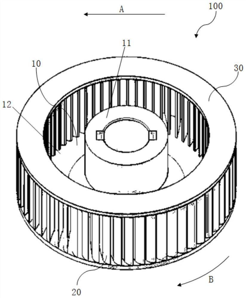
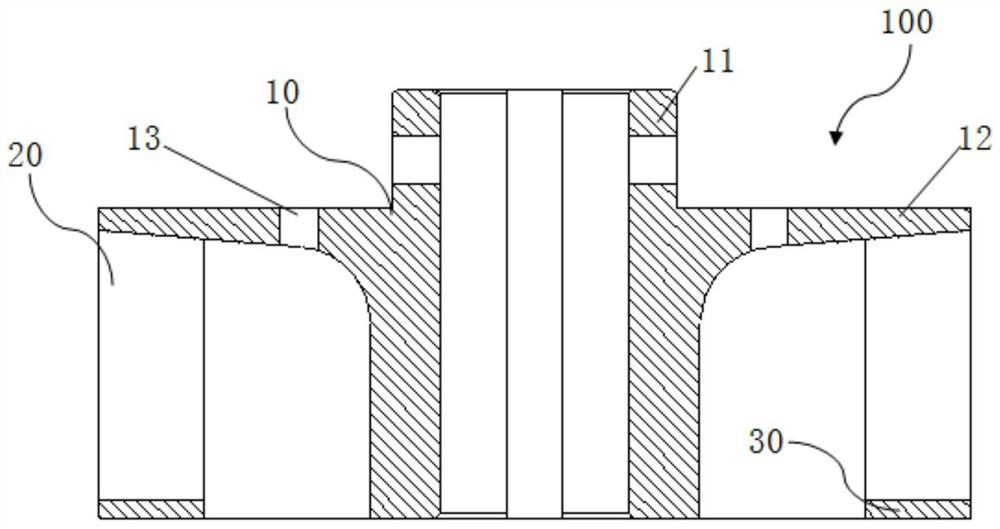
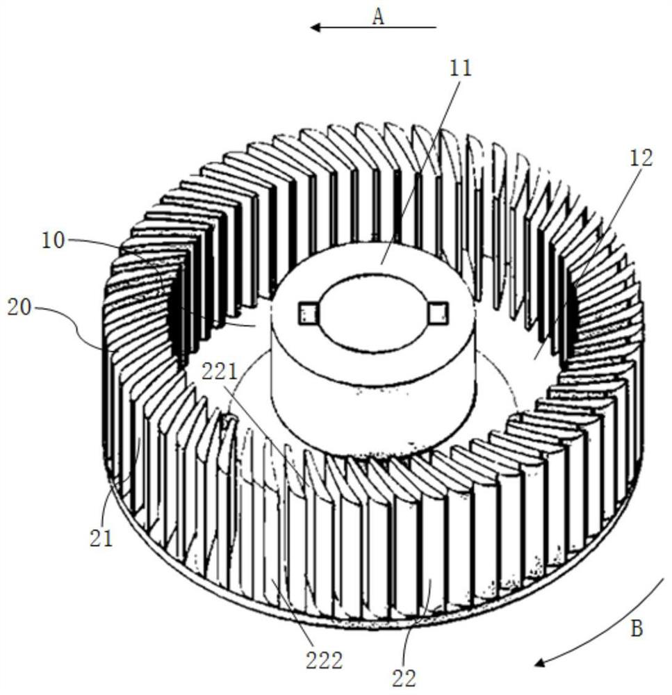
[0022] Such as figure 1 and figure 2 As shown, an aerodynamic impeller 100 in this embodiment is driven by external airflow and includes a hub 10 , blades 20 and blade guards 30 .

[0023] In this embodiment, the direction of the external airflow is A, and the rotation direction of the pneumatic impeller 100 driven by the external airflow is B.

[0024] The hub 10 includes a shaft passing portion 11 , a blade mounting plate 12 and a pressure balance hole 13 .

[0025] In this embodiment, the shaft passing portion 11 is a ...


PUM


Abstract

The invention belongs to the field of impellers, and discloses a pneumatic impeller which comprises a blade, the blade is provided with a blade basin surface and a blade back surface which are in arc connection, the blade back surface is provided with a front edge part and a flow guide part which are in arc connection, the curvature radius of the blade basin surface is 70%-90% of that of the flow guide part, and the curvature radius of the front edge part is 4.3%-5.5% of that of the flow guide part. The surface of the blade basin surface is provided with a first preset point, the surface of the flow guide part is provided with a second preset point, the first preset point and the second preset point are both located on the same cross section of the hub and are both located on a circumference with the center of the hub as the circle center, and a straight line which passes through the first preset point and is tangent to the surface of the blade basin surface serves as a first tangent line; a straight line passing through the center of the hub and the first preset point serves as a reference line, a straight line passing through the second preset point and tangent to the surface of the flow guide part serves as a second tangent line, the acute angle formed by the first tangent line and the second tangent line ranges from 6 degrees to 8 degrees, and the acute angle formed by the first tangent line and the reference line ranges from 30 degrees to 33 degrees.

Description

technical field [0001] The invention belongs to the field of impellers, in particular to a pneumatic impeller. Background technique [0002] The low-voltage start-up differential pressure power generation technology is a key new technology to solve the problem of low cost, safety, convenience and self-power supply of natural gas pressure regulating stations in cities and remote areas. [0003] Its implementation is specifically to drive the aerodynamic impeller to rotate through the external airflow, and then the rotating aerodynamic impeller provides sufficient torque for the generator, so that the generator can effectively output power to the outside. [0004] But at present, the pressure difference condition of this implementation must be greater than or equal to 0.4MPa, otherwise it cannot provide sufficient torque for the generator, so that the generator cannot effectively output power, and this 0.4MPa limitation has troubled the industry for a long time , so that a la...

Claims


Application Information

Patent Timeline
IPC IPC(8): F01D5/04F01D5/14F01D5/02
CPCF01D5/04F01D5/027F01D5/141F01D5/02
Inventor 张敏良方宇刘晓峰
Owner SHANGHAI UNIV OF ENG SCI
Learn More