

Sealing testing machine for cable protection pipe
A technology of cable protection tube and sealing test, which is applied in the direction of fluid tightness test, machine/structural component test, liquid tightness measurement using liquid/vacuum degree, etc., which can solve the problem of low accuracy and versatility of test results Low efficiency, low work efficiency and other problems, to achieve the effect of expanding the scope of application, reducing costs and improving accuracy
- Summary
- Abstract
- Description
- Claims
- Application Information
AI Technical Summary
Problems solved by technology
Method used
Image

Examples
Embodiment 1
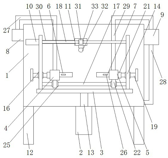
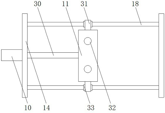
[0022] as attached Figure 1-4As shown, a cable protection pipe sealing test machine includes a water tank 1, a hydraulic cylinder 2, a load plate 3, a fixed block 4, a fixed block 5, a connecting pipe 6, a connecting pipe 2 7, a blower 8, and a water pump 9. Hydraulic cylinder 2 10 and moving block 11, characterized in that: the water tank 1 is set on the bracket 12, the hydraulic cylinder 1 2 is set at the bottom of the water tank 1, and the hydraulic cylinder 1 2 is equipped with a piston rod 1 13, and the piston rod one 13 is vertically extended into the water tank 1, the bearing plate 3 is arranged on the piston rod one 13, a vertical plate 14 is arranged on the bearing plate 3, and a fixing nut is arranged on the vertical plate 14 16, and between the vertical plate 14 and the vertical plate 14, a lower cross bar 17 and an upper cross bar 18 are provided, and a connecting ring 21 is provided on one side of the fixed block one 4, and a slider is provided at the bottom of t...
Embodiment 2
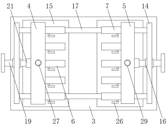
[0029] as attached Figure 5-6 As shown, a cable protection pipe sealing test machine includes a water tank 1, a hydraulic cylinder 2, a load plate 3, a fixed block 4, a fixed block 5, a connecting pipe 6, a connecting pipe 2 7, a blower 8, and a water pump 9. Hydraulic cylinder 2 10 and moving block 11, characterized in that: the water tank 1 is set on the bracket 12, the hydraulic cylinder 1 2 is set at the bottom of the water tank 1, and the hydraulic cylinder 1 2 is equipped with a piston rod 1 13, and the piston rod one 13 is vertically extended into the water tank 1, the bearing plate 3 is arranged on the piston rod one 13, a vertical plate 14 is arranged on the bearing plate 3, and a fixing nut is arranged on the vertical plate 14 16, and between the vertical plate 14 and the vertical plate 14, a lower cross bar 17 and an upper cross bar 18 are provided, and a connecting ring 21 is provided on one side of the fixed block one 4, and a slider is provided at the bottom of ...
PUM
 Abstract
Description
Claims
Application Information