Tilt rotor testing device

A test device, a technology for tilting rotors, which is applied in measurement devices, aircraft component testing, mechanical component testing, etc., can solve the transition process of large differences, cannot simulate the tilting of the rotor, and cannot simulate the transition process of the tiltrotor, etc. problems, to achieve the effect of improving the convenience of installation and ensuring the strength of the overall structure

Active Publication Date: 2022-03-11
NANJING UNIV OF AERONAUTICS & ASTRONAUTICS
View PDF11 Cites 2 Cited by
  • Summary
  • Abstract
  • Description
  • Claims
  • Application Information

AI Technical Summary

Problems solved by technology

Existing technology can measure the aerodynamic force generated by the rotor, but cannot simulate the transition process unique to the tilt rotor aircraft
The Chinese patent with the application number 202010413232.5 discloses a test bench for a tilt-rotor UAV. In this solution, a steering gear is provided. The output shaft of the steering gear is connected to the tilting shaft through a swing assembly, and the output shaft of the steering gear drives the machine base. The fixed plate rotates around the tilting axis, that is to say, the scheme utilizes the drive of the steering gear to realize the tilting of the rotor, but it can only realize the tilting of the rotor in one direction, but in fact the rotor still has a roll towards different directions , therefore, the simulation test of this scheme is quite different from the actual working conditions, and cannot simulate the real transition process of rotor tilting

Method used


Image

  • Tilt rotor testing device
  • Tilt rotor testing device
  • Tilt rotor testing device

Examples


Embodiment Construction

[0031] The following will clearly and completely describe the technical solutions in the embodiments of the present invention with reference to the accompanying drawings in the embodiments of the present invention. Obviously, the described embodiments are only some, not all, embodiments of the present invention. Based on the embodiments of the present invention, all other embodiments obtained by persons of ordinary skill in the art without making creative efforts belong to the protection scope of the present invention.

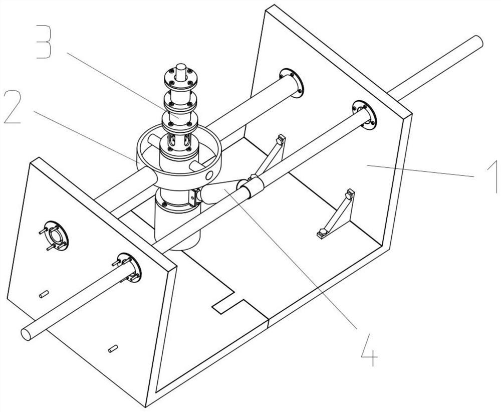
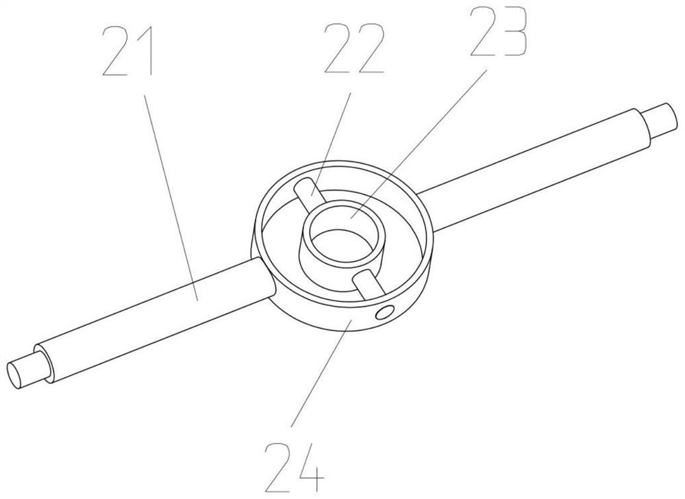
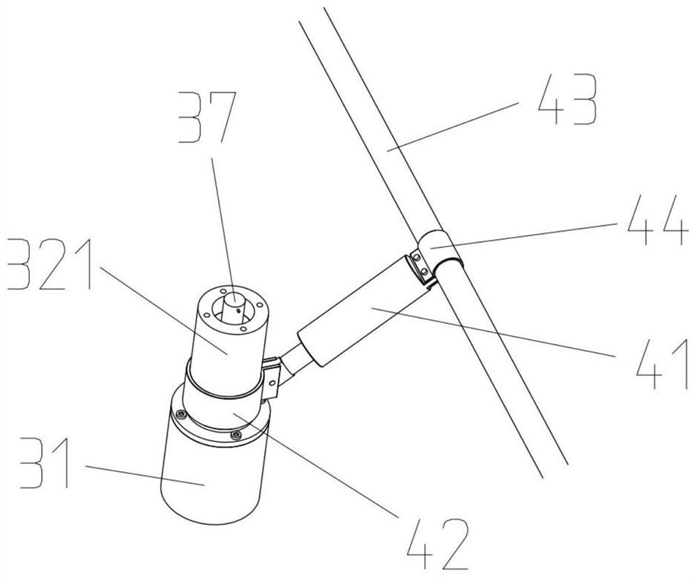
[0032] The purpose of the present invention is to provide a kind of tilting rotor test device, to solve the problems existing in the prior art, by installing the rotor measuring structure on a rotating shaft of the universal joint structure, realize the multi-degree-of-freedom rotation of the rotor measuring structure, in Driven by the tilting drive structure, the tilting of the rotor measurement structure can be controlled, and then the tilting process of the ...


PUM


Abstract

The invention discloses a tilt rotor test device, which comprises a rack, a universal hinge structure, a rotor measurement structure and a tilt driving structure, and is characterized in that the universal hinge structure comprises a first rotating shaft and a second rotating shaft which are perpendicular to each other, the first rotating shaft is mounted on the rack, and the rotor measurement structure is mounted on the second rotating shaft; the driving end of the tilting driving structure can drive the rotor measuring structure to rotate around the first rotating shaft, and the supporting end of the tilting driving structure can move in the direction parallel to the first rotating shaft; the rotor measuring structure is installed on one rotating shaft of the universal hinge structure, multi-degree-of-freedom rotation of the rotor measuring structure is achieved, tilting of the rotor measuring structure can be controlled under the driving effect of the tilting driving structure, the tilting working process of a rotor can be simulated, and the test accuracy is improved. And different side inclination directions of the rotor wing are realized by virtue of movement of the supporting end of the tilting driving structure, so that a working condition which is closer to the actual condition is simulated, and more effective data are obtained.

Description

technical field [0001] The invention relates to the technical field of aircraft testing, in particular to a tilt rotor test device. Background technique [0002] Tilting rotor aircraft has both the vertical flight capability of a helicopter and the high-speed cruise capability of a fixed-wing aircraft, and has great application prospects in the military and civilian fields in the future. However, the aerodynamic environment of the tiltrotor is very complex, and conventional theoretical methods are difficult to calculate the results of the highly unsteady flow field. Experiments are a common way to simulate the flow field in the design stage. Current aerodynamic tests rely on wind tunnels and matching testing equipment. The direction of the rotor axis of the tilt rotor can be changed during the flight, so the test device and test equipment are required to simulate the transition process of the tilt and measure the aerodynamic load of the rotor during this process. [0003] ...

Claims


Application Information

Patent Timeline
Patent Type & Authority Applications(China)
IPC IPC(8): G01M13/00B64F5/60
CPCG01M13/00B64F5/60Y02T90/00
Inventor 张夏阳周旭招启军林沐阳王博陈希赵国庆
Owner NANJING UNIV OF AERONAUTICS & ASTRONAUTICS
Why Eureka
Try Eureka