
Ground seismic source excitation system based on microwave radar and seismic data acquisition method

A microwave radar and excitation system technology, which is applied in the field of seismic exploration, can solve the problems of uncertainty in the landing time and location of the source body, increased workload, and high cost, and achieves the effect of data acquisition and seismic excitation.

Pending Publication Date: 2022-03-11
中国地质调查局地球物理调查中心
View PDF0 Cites 0 Cited by
  • Summary
  • Abstract
  • Description
  • Claims
  • Application Information

AI Technical Summary

Problems solved by technology

Theoretically speaking, the released seismic source body moves freely from high altitude and lands on the projected position of the UAV on the ground, which is the pre-set coordinates of the excitation point; Influenced by factors such as aircraft attitude, weather (mainly wind), air resistance, and source body shape, the landing time and position of the source body are uncertain. The time point of the source body landing must be measured in real time and the seismic data must be recorded simultaneously.
[0003] The traditional synchronous recording methods and devices cannot be used directly, and it is difficult to meet the requirements of relevant specifications for seismic exploration at this stage
If the excitation device is embedded inside the source body, when the source body hits the ground at high speed, a strong collision will easily damage the internal structure of the excitation device, the reuse rate is low, and the cost is high
Relying on the vibration sensor control on the ground, affected by the induced electromotive force and the ground medium, the sensitivity of the vibration sensor needs to be adjusted according to the actual situation, which increases the workload and is prone to artificial delay or error affecting data quality

Method used


Image

  • Ground seismic source excitation system based on microwave radar and seismic data acquisition method
  • Ground seismic source excitation system based on microwave radar and seismic data acquisition method

Examples


Embodiment Construction

[0030] The implementation mode of the present invention is illustrated by specific specific examples below, and those who are familiar with this technology can easily understand other advantages and effects of the present invention from the contents disclosed in this description. Obviously, the described embodiments are a part of the present invention. , but not all examples. Based on the embodiments of the present invention, all other embodiments obtained by persons of ordinary skill in the art without making creative efforts belong to the protection scope of the present invention.

[0031] Terms such as "upper", "lower", "left", "right", and "middle" quoted in this specification are only for the convenience of description, and are not used to limit the scope of the present invention. The change or adjustment of the relative relationship shall also be regarded as the implementable scope of the present invention without substantive change of the technical content.

[0032] Su...


PUM


Abstract

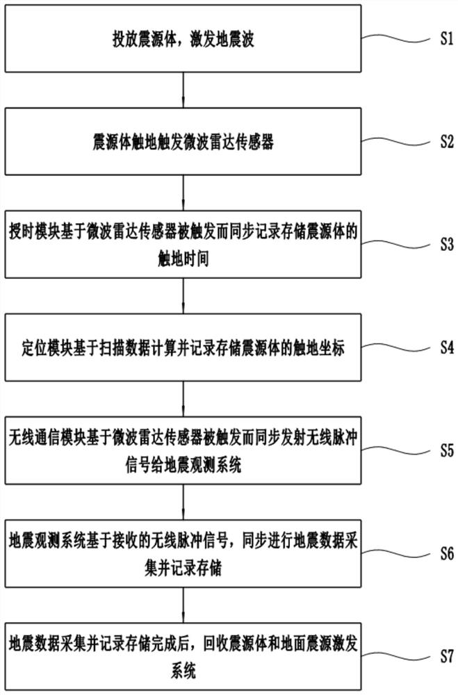
The invention discloses a ground seismic source excitation system based on a microwave radar and a seismic data acquisition method, and the system comprises a microwave radar sensor which is used for transmitting a microwave signal, forming an induction scanning area around, and is triggered based on the shielding of the microwave signal when a seismic source body touches the ground; the time service module synchronously records and stores the grounding time of the seismic source body on the basis that the microwave radar sensor is triggered; the positioning module is used for calculating, recording and storing grounding coordinates of the seismic source body based on the scanning data; and the wireless communication module synchronously transmits a wireless pulse signal to the seismological observation system based on the triggering of the microwave radar sensor, so that the seismological observation system synchronously carries out seismic data acquisition. Timing and / or positioning of seismic source body landing excitation are / is realized, the seismological observation system is controlled to synchronously carry out data acquisition, and synchronization of data recording and seismic excitation is realized.

Description

technical field [0001] The invention relates to the technical field of seismic exploration, in particular to a ground seismic source excitation system based on microwave radar and a seismic data acquisition method based on the system. Background technique [0002] During seismic exploration, it is necessary to record the firing position and time of the shot point, so as to provide reliable spatial and temporal information for data processing and interpretation. The UAV source excitation system is a relatively new source excitation system. The UAV is controlled by the ground station to automatically navigate to the sky above the coordinate position of the excitation point, and the source body is dropped. The source body hits the ground at high speed to stimulate seismic waves, which can be used in complex environments. Rapid and high-quality seismic data acquisition can be achieved in working areas where artificial seismic sources cannot work or where the excitation effect is...

Claims


Application Information

Patent Timeline
Patent Type & Authority Applications(China)
IPC IPC(8): G01V1/147G01V1/18G01V1/22G01S13/88
CPCG01V1/147G01V1/18G01V1/223G01S13/885
Inventor 宋炯杨煜坤任堃马德锡陈孝强范俊杰夏锐康建坤徐昊
Owner 中国地质调查局地球物理调查中心
Learn More