Photoelectric composite cable connector for oil well annulus test

A technology for optoelectronic composite cables and connectors, which is applied in the direction of connection, coupling of optical waveguides, and components of connecting devices, etc. Effect

Pending Publication Date: 2022-03-11
山东希尔电缆有限公司 +1
View PDF0 Cites 0 Cited by
  • Summary
  • Abstract
  • Description
  • Claims
  • Application Information

AI Technical Summary

Problems solved by technology

[0005] The object of the present invention is to provide a photoelectric composite cable connector for oil well annulus testing. The helically wound optical fiber composite cable connected to the helically wound optical fiber composite cable can be used for temperature monitoring on the ground or in oil well annulus testing. Semi-permanent monitoring or permanent monitoring of parameters such as pressure, flow velocity, vibration, sound wave, strain, etc., to overcome the shortcomings of the existing single function and purpose of the existing inner steel pipe clamp connector and optical cable outer ferrule connector

Method used


Image

  • Photoelectric composite cable connector for oil well annulus test
  • Photoelectric composite cable connector for oil well annulus test
  • Photoelectric composite cable connector for oil well annulus test

Examples


Embodiment Construction

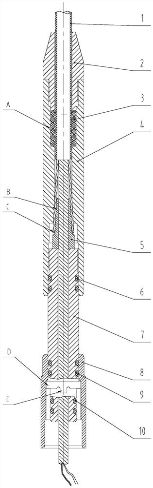
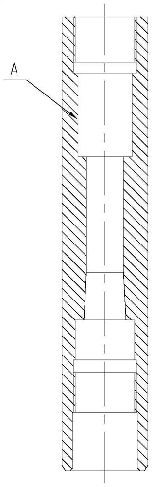
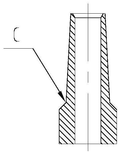
[0014] Such as Figure 1 to Figure 5 As shown, this embodiment specifically discloses a photoelectric composite cable connector for oil well annulus testing, including an upper joint 4, which is characterized in that: the upper joint 4 is in the shape of a sleeve, and the upper joint 4 passes through In the photoelectric composite cable 1, the minimum inner diameter of the upper joint 4 is consistent with the outer diameter of the photoelectric composite cable 1. The upper end of the upper joint 4 has an internal thread and a sealing ring groove A, and the lower end of the upper joint 4 has an inner taper hole, an internal thread and a sealing ring. On the ring surface, the inner tapered hole of the upper joint 4 is provided with a tapered sleeve 5, and the outer armored steel wire B of the photoelectric composite cable 1 is clamped between the inner tapered hole of the upper joint 4 and the outer tapered surface of the tapered sleeve 5, and the upper joint The lower part of 4...


PUM


Abstract

The invention discloses a photoelectric composite cable connector for an oil well annulus test, and relates to the technical field of the photoelectric composite cable connector for the oil well annulus test, which is matched with a photoelectric composite cable and a spiral winding type optical fiber composite cable connector for use, and the photoelectric composite cable connector comprises an upper joint and is characterized in that the upper joint is in a pipe sleeve shape; a photoelectric composite cable penetrates through the upper connector, the minimum inner hole diameter of the upper connector is consistent with the outer diameter of the photoelectric composite cable, the upper end of the upper connector is provided with internal threads and a sealing ring groove, and the lower end of the upper connector is provided with an inner taper hole, internal threads and a sealing ring face. The photoelectric composite cable connector is reasonable in structural design and convenient to use, optical fiber welding and wire connection of a photoelectric composite cable can be achieved through the connector, large axial tension can be borne, and the problems of optical fiber welding, wire connection and fixing of the large axial tension of the photoelectric composite cable are solved.

Description

technical field [0001] The invention relates to the technical field of a photoelectric composite cable connector used in conjunction with a photoelectric composite cable and a spiral-wound optical fiber composite cable connector for oil well annulus testing, in particular to a photoelectric composite cable connector for oil well annulus testing . Background technique [0002] The optical fiber composite cable connector is mainly used for optical fiber fusion and wire connection of the optical fiber composite cable and the spiral wound optical fiber composite cable connector. The spiral wound optical fiber composite cable matched with the spiral wound optical fiber composite cable connector can be used on the ground or oil well Semi-permanent monitoring or permanent monitoring of parameters such as temperature, pressure, flow rate, vibration, sound wave, strain, etc. in annulus testing. [0003] At present, the existing photoelectric composite cables at home and abroad mainl...

Claims


Application Information

Patent Timeline
Patent Type & Authority Applications(China)
IPC IPC(8): H01R13/502H01R13/52H01R13/40G02B6/255G02B6/44
CPCH01R13/502H01R13/5202H01R13/40G02B6/2558G02B6/4439
Inventor 季昌芸田惠方刘奇江少帅姜再鹏刘晓超
Owner 山东希尔电缆有限公司
Why Eureka
Try Eureka